
simple steps for making fm transmitter

The FM transmitter circuit primarily consists of a single transistor, which serves as the amplifier and modulator. The transistor is typically an NPN type, such as the 2N3904 or BC547, which is capable of operating at the desired frequency range. The circuit also includes a power supply, usually a battery, which provides the necessary voltage and current for the operation of the transistor and other components.
The electret microphone acts as the audio input source, converting sound waves into electrical signals. The microphone's output is fed into the base of the transistor, where it is amplified. The variable capacitor, or trimmer capacitor, plays a crucial role in determining the transmitter's frequency. By adjusting this capacitor, the resonant frequency of the circuit can be modified, allowing for fine-tuning of the output frequency to avoid interference with other radio signals.
The circuit is completed with additional passive components, including resistors and capacitors, which help stabilize the transistor's operation and filter the audio signal. The transmission antenna can be as simple as a short wire, enhancing the circuit's ability to transmit signals over the specified range.
In summary, this FM transmitter project is an excellent introduction to radio frequency electronics, demonstrating fundamental principles of modulation and amplification. The simplicity of the design, along with the use of readily available components, makes it an ideal project for those new to electronics. Proper assembly and tuning of the circuit will yield a functional FM transmitter capable of broadcasting audio signals within the specified range.This tutorial is for making simplest FM transmitter using one transistor. You can make this project with less components and it is an easy and simple project for beginners. Before you proceed, please see the schematic given below. In the schematic, you will see the components required for making an FM transmitter. The transmission range of this cir cuit is approximately 10-20 meters. 3. Variable capacitor: VC1. It is also called trimmer capacitor. You can buy one from your local store. The capacitance range should be 0-100pF or 10-100pF. If you cannot get one, try to get a trimmer capacitor that has minimum capacitance of 20pF. You can also get such capacitor from your broken radio, but you may need assistance in getting that out from your radio. On your electret microphone, you will see that on one of the pins, there is solder pad connected to the case of microphone.
Remember that pin is always negative. On the image shown below, you can notice that I have not used a trimmer/variable capacitor. I have used a fixed 20pF capacitor instead. So, if you don`t have a variable capacitor, you can use a fixed capacitor also. Then, with a non-conductive tool, adjust the capacitor for the clearest reception, rotate it till the receiver receives a sound from the microphone of transmitter. Use the following formula for determining the frequency. 🔗 External reference
Related Circuits
This schematic represents an FM transmitter capable of delivering an output power of 3 to 3.5 W, operating within a frequency range of 90 to 110 MHz. While the stability of the circuit is acceptable, the integration of a...
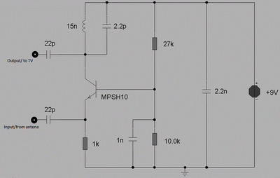
This circuit is designed to enhance RF signals from a television antenna operating at UHF frequencies in the range of 450-800 MHz. It provides a gain of approximately 10 dB, making it suitable for boosting weak TV signals. The...
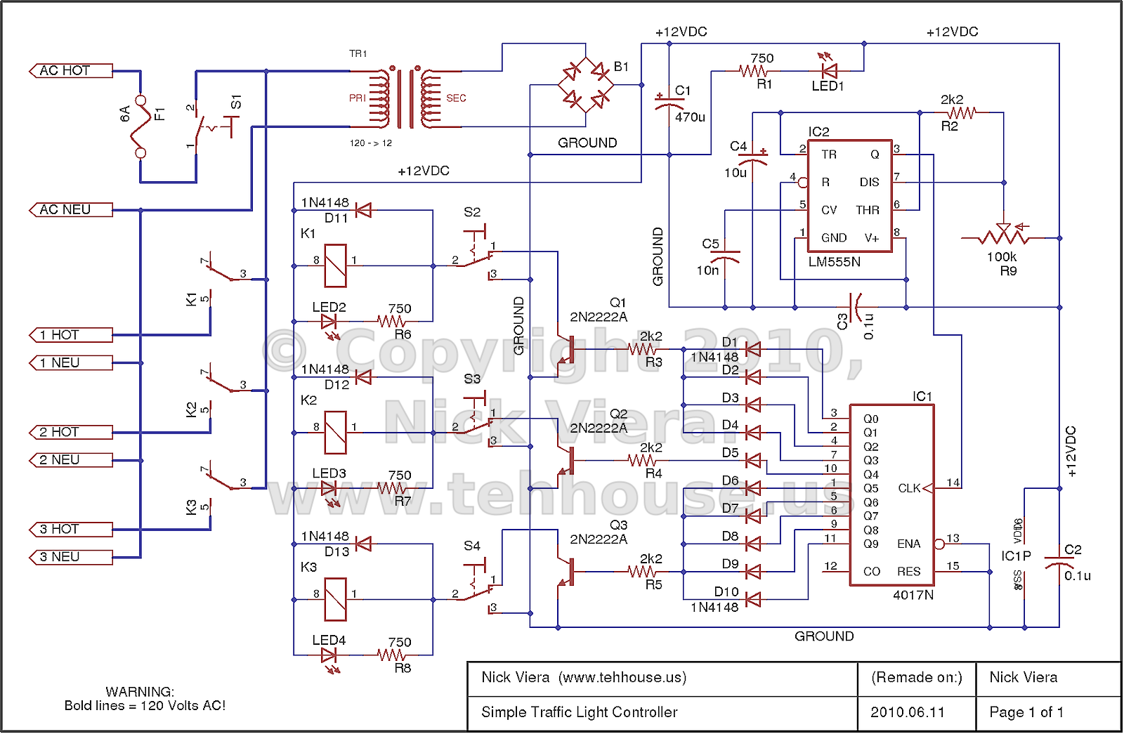
The controller is entirely hardware-based and provides the typical sequencing for a standard three-light traffic signal. This traffic light controller/sequencer was constructed during the initial learning phase of electronics. Although it may be considered crude and unattractive, it effectively...
These two tank circuits appear to broaden the operating spectrum. The accompanying information sheet indicates that when both circuit stages oscillate at the same frequency, the power output reaches its maximum. This suggests that if the tunable tank circuit...
This transmitter utilizes a 5089 DTMF generator chip along with a keypad to produce DTMF signals, which are then modulated onto an infrared (IR) light beam emitted from an IR LED. The circuit employs a 3.579-MHz TV burst crystal...
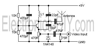
This is a simple video transmitter capable of transmitting signals up to 50 meters. It can be connected to a camera or other video sources, allowing viewing on a VHF channel analog TV. The transmitter operates on a supply...