
Clap operated Remote Control for Fans with description

The clap-operated remote control system utilizes sound recognition to activate the fan's speed settings. The core component of the system is a sound sensor, typically a microphone or a specialized sound detection module that can recognize the specific frequency and amplitude of a clap. When the sound sensor detects a clap, it sends a signal to a microcontroller, which processes the input and adjusts the fan speed accordingly.
The circuit diagram for this system includes several key components: the sound sensor, the microcontroller, a motor driver, and the fan itself. The sound sensor is connected to the microcontroller's input pin, allowing it to monitor for clap sounds. The microcontroller is programmed to interpret the sound input and control the motor driver, which in turn regulates the power supplied to the fan motor.
The motor driver is essential for managing the fan's speed, as it can handle the higher currents required by the fan motor. It receives commands from the microcontroller to switch between different speed settings, allowing for a total of ten distinct speeds. This is typically achieved using a pulse-width modulation (PWM) technique, which adjusts the average power delivered to the motor, thus controlling the fan speed smoothly.
Additionally, the circuit may include a power supply unit to ensure that all components receive the necessary voltage and current for operation. Proper filtering and decoupling capacitors may be included to stabilize the power supply and reduce noise, enhancing the reliability of the system.
Overall, this clap-operated remote control for fans offers a convenient and innovative way to adjust fan speeds without the need for physical interaction, making it particularly useful in situations where hands-free operation is desirable.Clap operated Remote Control for Fans in this website is used control ten-step speed of fan circuit diagram and description of Clap operated Remote Control for Fans. 🔗 External reference
Related Circuits
The following circuit illustrates a stepper motor controller based on the PIC16F84A integrated circuit. It features a transistor used for driving the motor. The stepper motor controller circuit utilizes the PIC16F84A microcontroller, which is a popular choice for controlling stepper...
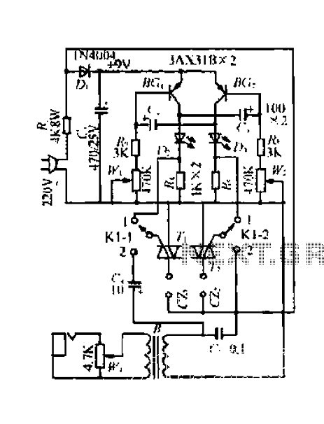
A 220V mains power supply is reduced using a control circuit designed by N. Guanidine D. Yi. The circuit features a spike Bode and provides a +9V voltage supply. It includes components such as a control port (G), a...
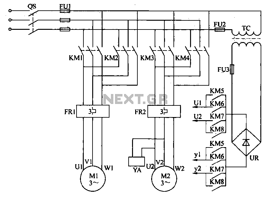
Electric driving is essential for modernizing plant material transport. Traditional control methods are primarily semi-manually operated automatic systems. To enhance efficiency, promote production automation, and reduce labor intensity, electrical automation for material transport is often implemented. This automation allows...
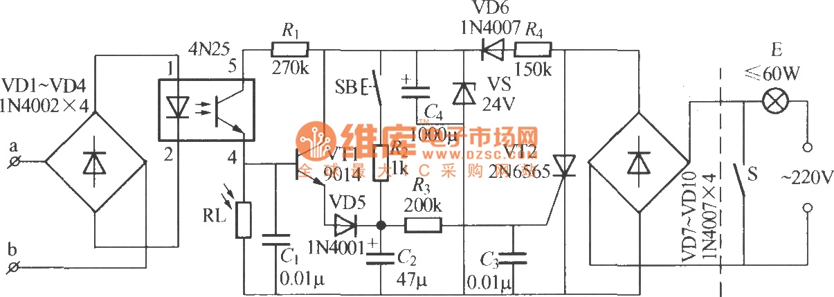
The diagram illustrates an automatic lighting control circuit activated by a telephone. At night, when the telephone rings or the user picks up the receiver, the light turns on. If the telephone stops ringing (when no one is listening)...
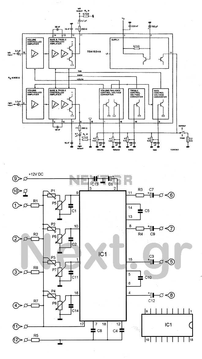
The circuit utilizes the TDA1524 chip, which is an integrated control unit for volume, bass, treble, and balance adjustments. Control is achieved through four potentiometers (P5-P8). The integrated circuit IC1 requires very few external components to operate. Potentiometers P1-P4...
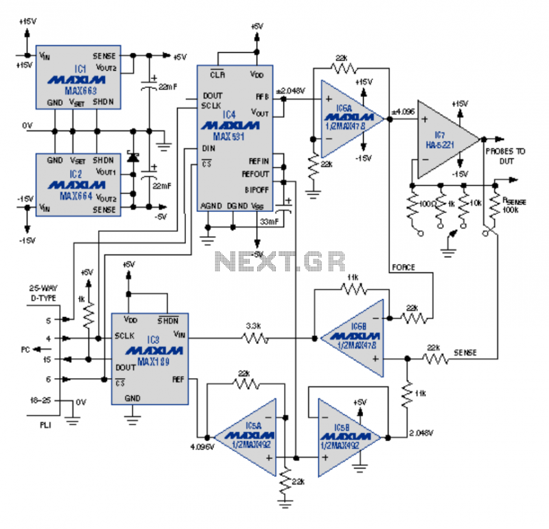
This article describes an I-V curve tracer circuit that uses a computer for display and control. The circuit is controlled via the PC parallel port. Software is provided, written in BASIC, to control the measurement and display the results...