
Class-A 100W Amplifier

The original simple 1969 JLH class-A design provided excellent first cycle accuracy through mid and high frequencies (dynamic clarity) because there were no stabilization components nor a series output choke, whilst the NFB error correction was established via the input emitter (some describe this as current feedback). However, it did generate rather a lot of heat, the damping was soft at lower frequencies and the positive slew was weaker in the presence of loudspeaker system generated back-EMF at higher audio frequencies.
The Class A and Class AB amplifier circuit described operates at a power rating of 100 Watts into a 4-ohm load, making it suitable for driving high-performance loudspeakers. The design draws on the principles established in the original JLH class-A amplifier, which is known for its simplicity and high fidelity. The absence of stabilization components and output chokes contributes to the amplifier's ability to deliver dynamic audio with minimal distortion, particularly in the mid and high frequency ranges.
In this design, the feedback mechanism employs current feedback through the input emitter, which enhances the amplifier's responsiveness to audio signals, thereby improving the overall sound quality. This configuration allows for a more direct interaction between the input signal and the output stage, resulting in improved transient response and clarity.
However, the inherent characteristics of Class A operation lead to significant heat generation, necessitating adequate thermal management solutions such as heat sinks or active cooling systems. The soft damping effect observed at lower frequencies can be mitigated through careful selection of the output stage components, allowing for improved control over the loudspeaker's movement, which is crucial for achieving tight bass response.
In higher frequency ranges, the issue of back-EMF generated by the loudspeaker can introduce challenges in maintaining positive slew rates. To address this, the circuit may incorporate additional measures, such as improved feedback paths or compensatory circuitry, to enhance the amplifier's performance under dynamic load conditions.
Overall, this amplifier design exemplifies a balance between classic audio engineering principles and modern enhancements, aiming to deliver high-quality audio reproduction while addressing the thermal and dynamic challenges associated with high-power amplification.A Class A // Class AB amplifier rated 100 Watts when driving a 4 ohm loudspeaker. This circuit developed out of my 30+ years of JLH class-A based investigations. The original `simple` 1969 JLH class-A design provided excellent first cycle accuracy through mid and high frequencies (dynamic clarity) because there were no stabilisation components nor a series output choke, whilst the NFB error correction was established via the input emitter (some describe this as current feedback). However it did generate rather a lot of heat, the damping was `soft` at lower frequencies and the positive slew was weaker in the presence of loudspeaker system generated back-EMF at higher audio frequencies. I was eventually able to improve upo 🔗 External reference
Related Circuits
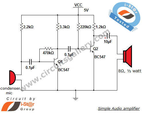
This circuit diagram is a simple and effective design for amplifying weak signals from a capacitive condenser microphone. It is suitable for sound sensing applications and various automatic robotic sensors. While a more complex audio amplifier circuit using the...
If you want to test an amplifier, a dummy load may be more convenient for speakers to use than actual speakers, due to noise or damage to the speakers. This circuit behaves in terms of impedance and frequency response...
This is an operational amplifier (Op-Amp) oscillator circuit. This circuit has several advantages, including its ability to operate at low frequencies. The operational amplifier oscillator circuit is designed to generate a periodic waveform output, typically a sine or square wave,...

A compact audio amplifier circuit utilizing the TDA 7052 integrated circuit from Philips. This circuit is suitable for use as a pocket radio amplifier, delivering an output power of 2 watts. The TDA 7052 is a low-voltage audio amplifier designed...

This integrated circuit (IC) chip is specifically designed for power boosting applications in automobiles. It features self-protection mechanisms against short circuits and thermal issues. In the bridge configuration depicted, it can deliver 20 watts of power to a 2-ohm...

A lens is a custom view of the content in the repository. It can be considered a sophisticated type of list that allows users to view content through the perspectives of trusted organizations and individuals. Class D amplifiers exhibit...