
Class-A Tube Headphone Amplifier
A tube rectifier is employed in this project because the rectifier tube implements a slow turn-on characteristic for the amplifier tubes and eliminates turn-on cracks. When using tube rectification (EZ80) with only one supply voltage, it is necessary to implement full wave rectification with two additional diodes (1N4007). The cathode of the rectifier tube is connected to the capacitor 47µF /450V and a 20Hy choke with at least 50mA current specification. The 47µF capacitor should be of high quality and rated at least with 400V because the periodic current loads are the highest for this capacitor. The output capacitors are a combination of electrolytic (1000µF/400V) and foil (1.5µF and 100nF MKP) types. The 220K/2W resistor should be soldered near and directly to the big electrolytic capacitor to discharge the capacitor when there is no load. The tube for the input section is the double triode ECC88 or 6DJ8. Better versions are the E88CC, CCa or 6922 or even with less noise the E188CC or 7308. There are many brands NOS and from current productions available. The type of tube has µ = 33, S=12.5mA/V and Ri=2k6. Nearly equivalent is the Russian 6N1P which has slightly differing specifications.
The tube for the output section is the double triode E288CC or 8223. This tube is sometimes falsely referred to as a replacement for the E88CC type of tubes. Despite that this tube has only µ = 25, the operating current must be much higher. Furthermore, the inner resistance Ri = 1k25 is less. The plate voltage is about the same as for the E88CC type. For the headphone amplifier output section, this tube is very well suited. Relatively low plate voltage, a current of 20mA for each triode is far below the maximum power limit and with S = 20mA/V the output impedance of the parallel connected cathode follower is 1/(2 S) = 25 Ohm. This tube is a special quality double triode with a tested life time of 10,000 hours, gold pins, and with a noval socket. The rectifier tube EZ80 could be replaced with the 6V4 or any other tube with the same or even higher current range. The EZ80 is rated for a maximum current of 90mA. Therefore there is a margin when using two tubes, one for each channel respectively. With less lifetime, one tube for both channels could be used, which is not recommended. Using one tube for both channels, the better solution would be to use the EZ81 or 6CA4 with a maximum current of 150mA. Using other tubes than the EZ80 could lead to a different voltage drop at the rectifier diodes and therefore the plate voltage would change or this has to be taken into account and the secondary voltage of the transformer would have to be adapted correspondingly.
Low output impedance and a relatively high current for the output sections are needed to drive headphones, and in connection with the condition that only a few tube types are suitable. These conditions could be fulfilled very well with the 6DJ8, ECC88 tube type family. An operating point with a plate voltage of only 80V is well between the limits, and the gain µ of 33 is adequate. For the parallel connected cathode follower, the E288CC is well suited, delivering higher currents and an output impedance of 25 Ohm. The voltage at the output coupling capacitor could be with this tube about 40V.Pure Class-A triode OTL design and only one tube for amplification. The plate voltages should be low. The output impedance should be as low as possible and the maximum output current should be as high as possible. This amplifier is a stand alone Headphone amplifier without the property of input selection as mentioned in my previous project but could be expanded if desired.
Preferring the Class-A OTL design I decided again to implement a long tailed pair for the input section and a parallel connected cathode follower for the output section. The voltages should be as low as possible. This condition was taken into account mainly because the risk of any high voltages at the output of the amplifier, if any damage occurs, should be kept as low as possible.
This could be the case if the output capacitor shortens and then the full cathode voltage would be connected direct to the output, damaging the headphone or there would be the risk of touching lethal voltages! In my opinion it's better that this voltage is 40V and not 150V or even higher. The audio input is connected to a volume potentiometer (47K log, ALPS, Noble or Panasonic) and then coupled with a 220nF MKP capacitor to a long tailed pair with the E88CC triodes .
The long tailed pair delivers a signal which is not phase inverted and therefore the whole amplifier is not phase inverted. Pin 7 is connected to ground, because the amplifier is designed for asymmetrical input signals. If an upgrade to symmetrical signals is desired pin 7 could be connected to the second input signal. The 1M resistor connects the grid of the first triode to ground and the 100 Ohm resistor blocks RF oscillation of the circuit.
The common cathode resistor with 180 Ohm sets the operating current of 5mA for each triode and the plate resistors 7k5 set the plate voltages of about 80V. The anode of the second triode is connected to the 220nF coupling capacitor. The output section is a parallel connected E288CC cathode follower. The 470K, 33 Ohm and 1K/3W resistors set the operating point of the tubes (about 76V plate voltage and 21mA plate current).
The cathodes are connected to the output coupling capacitors 470µF/400V and 1µF/400V. The output resistor 4k7/1W pulls the output to ground if no load is connected. The supply was build up for each channel separately, only the power transformer is used for both channels (Figure 2). To save money I decided to serial connect the secondaries of two easy gettable toroidal transformers.
The primaries are connected in parallel. Two smaller transformers instead of one big transformer have the additional advantage that they can be placed very space saving into the chassis. The serial connection of 2x18V and 2x55V transformers gave under load an AC voltage of about 167V. I used a tube rectifier for this project, because the rectifier tube implements a slow turn-on characteristic for the amplifier tubes and eliminates turn-on cracks.
In my first project, I used a lot of electronics to do this job. When using tube rectification (EZ80) with only one supply voltage it is necessary to implement full wave rectification with two additional diodes (1N4007). The cathode of the rectifier tube is connected to the capacitor 47µF /450V and a 20Hy choke with at least 50mA current specification.
The 47µF capacitor should be of high quality and rated at least with 400V because the periodic current loads are the highest for this capacitor. The output capacitors are a combination of electrolytic (1000µF/400V) and foil (1,5µF and 100nF MKP) types.
The 220K/2W resistor should be soldered near and directly to the big electrolytic capacitor to discharge the capacitor when there is no load. The tube for the input section is the double triode ECC88 or 6DJ8. Better versions are the E88CC, CCa or 6922 or even with less noise the E188CC or 7308. There are many brands NOS and from current productions available. I have good experience with Philips ECC88 NOS and JAN-Philips 6922. This type of tube has µ = 33, S=12.5mA/V and Ri=2k6. Nearly equivalent is the Russian 6N1P which has slightly differing specifications. The tube for the output section is the double triode E288CC or 8223. This tube is sometimes falsely referred as a replacement for the E88CC type of tubes. Despite that this tube has only µ = 25 the operating current must be much higher. Furthermore the inner resistance Ri = 1k25 is less. The plate voltage is about the same as for the E88CC type. For the headphone amplifier output section this tube is very well suited. Relatively low plate voltage, a current of 20mA for each triode is far below the maximum power limit and with S = 20mA/V the output impedance of the parallel connected cathode follower is 1/(2 S) = 25 Ohm.
This tube is a special quality double triode with a tested life time of 10 000 hours, gold pins and with a noval socket. I used Siemens NOS and the operating point matched instantly the data sheet very closely. I can really recommend this tube. The rectifier tube EZ80 could be replaced with the 6V4 or any other tube with the same or even higher current range.
The EZ80 is rated for a maximum current of 90mA. Therefore there is a margin when using two tubes, one for each channel respectively (the current demand for one channel is 52mA) . With less lifetime there could be used one tube for both channels which I would not recommend. Using one tube for both channels the better solution would be to use the EZ81 or 6CA4 with a maximum current of 150mA.
Using other tubes than the EZ80 would lead probably to an other voltage drop at the rectifier diodes and therefore the plate voltage would change or this has to be taken into account and the secondary voltage of the transformer would have to be adapted correspondingly. ad 3) Low output impedance and a relatively high current for the output sections are needed to drive headphones and in connection with the condition 1) and 2) only a few tube types are suitable.
These conditions could be fulfilled very good with the 6DJ8, ECC88 tube type family. An operating point with a plate voltage of only 80V is well between the limits and the gain µ of 33 is well enough. For the parallel connected cathode follower the E288CC is well suited, delivering higher currents and an output impedance of 25 Ohm.
The voltage at the output coupling capacitor could be with this tube about 40V. 🔗 External reference
Related Circuits
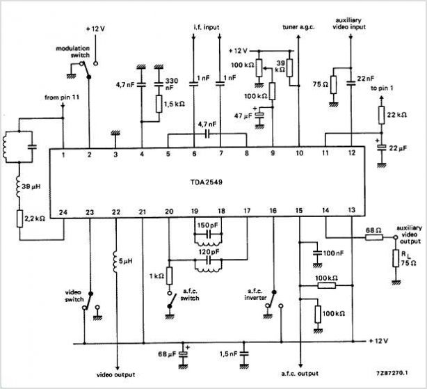
The circuits utilize two FM Demodulator TDA2555 systems to execute the demodulation functions necessary in a dual sound carrier television system for demodulating the sound carriers. The distinction between the TDA2555 and TDA2557 lies in the number of stages...
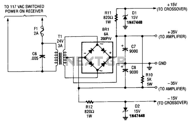
This power supply is designed to power a 100-W low-frequency amplifier and is capable of supporting various mono or stereo amplifiers within the medium power range, specifically those that require 30 to 35 V. The power supply circuit is engineered...

A battery-powered portable unit suitable for all types of televisions. This low-cost project allows audio reproduction from a TV without disturbing others. This battery-powered portable audio unit is designed to provide a convenient solution for reproducing television audio discreetly. The...
The amplifier features an adjustable gain, facilitated by R1, a 1 Mega Ohm variable resistor. This resistor regulates the feedback of the 741 operational amplifier (op-amp), which subsequently drives a 2N2222 output transistor. The circuit receives an audio signal...
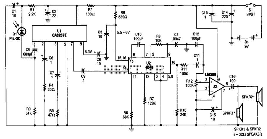
The infrared (IR) detector diode D1 captures the IR signal at approximately 40 kHz and transmits it to U1, a high-gain preamplifier, which then sends the signal to U2, a 4046 phase-locked loop (PLL) configured as a frequency modulation...
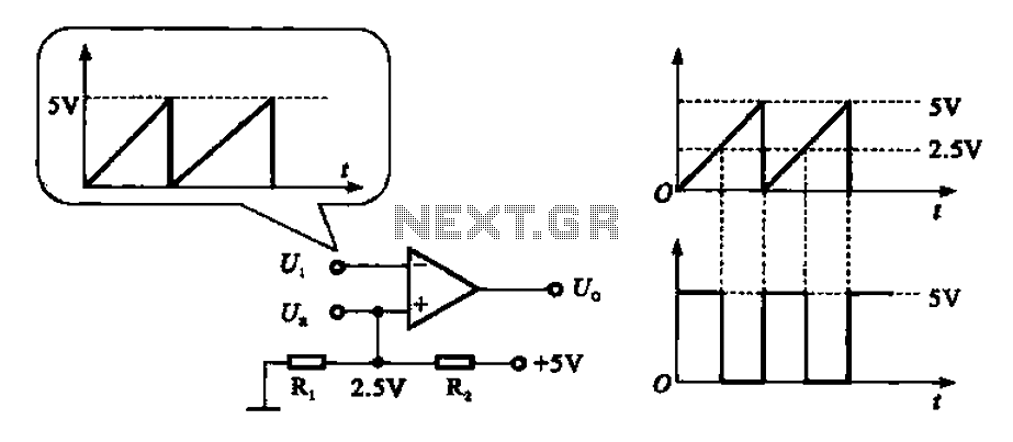
The addition and subtraction functions of an operational amplifier are facilitated through an external feedback network, which places the integrated operational amplifier in a deep state of negative feedback. In this linear region, the relationship between input and output...