
Sawtooth Generator Circuit with 741 IC

The sawtooth generator circuit primarily employs the 741 op-amp due to its versatility and availability. The configuration typically involves the op-amp in an integrator setup, where the output signal ramps up linearly and then quickly resets to produce the characteristic sawtooth waveform. The frequency of the sawtooth wave can be adjusted by varying the resistance and capacitance in the circuit, which is often accomplished using a variable resistor (P2).
In this circuit, the input signal is fed into the inverting terminal of the op-amp, while the feedback path includes a capacitor that charges and discharges based on the output voltage. As the capacitor charges, the output voltage rises, creating the linear ramp. Once the voltage reaches a predetermined threshold, the op-amp output switches states, causing the capacitor to discharge rapidly, resulting in the sharp drop characteristic of a sawtooth waveform.
The circuit may also include additional components such as diodes to protect against reverse polarity and resistors to set the gain of the op-amp. The output can be connected to a speaker or other audio processing equipment to produce sound. The frequency and amplitude of the output can be manipulated through the potentiometer and other passive components, allowing for a range of musical tones and effects to be synthesized. This makes the sawtooth generator a valuable tool in electronic music production and sound design.This sawtooth generator circuit use 741 IC and is used as a musical sound synthesizer. The sawtooth input signal is continously changed through P2 to a wav.. 🔗 External reference
Related Circuits
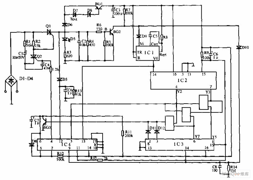
The pulse telephone 160 168 controller circuit is depicted above. This controller can be installed either on the telephone or on the switchboard of the trunk line. It effectively prevents unauthorized dialing of numbers 160 and 168. Diodes D1...
The circuit is designed to be low cost. It uses a PIC12C508 to perform the control functions and standard 40 kHz piezo transducers. The drive to the transmitting transducer can be simply driven directly from the PIC. The 5V...
The EUA2032 is a high-efficiency, 2.5W mono class-D audio power amplifier. A newly developed filterless PWM modulation architecture further reduces EMI and THD+N, as well as eliminates the LC output filter, thereby reducing the external component count, system cost,...
The FM302E-I-type FM transmitter exciter is utilized in Japan's NEC HPB a 1210 motherboard. It features direct carrier frequency modulation, phase-locked frequency stabilization, and frequency synthesis. The preamplifier (BLF-177 FET) is directly driven by an actuator, achieving a maximum...
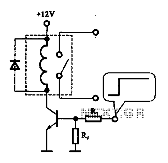
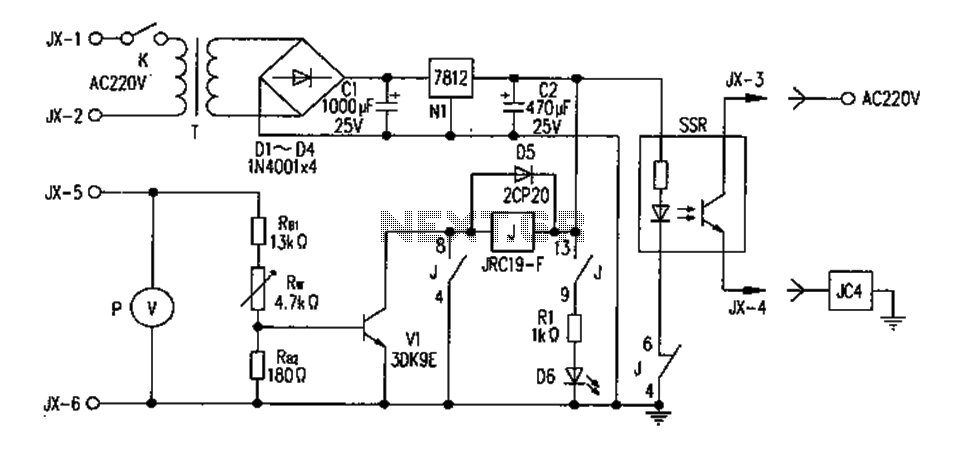
A relay control circuit is illustrated, which is commonly found in microwave switches. This circuit facilitates the operation of various components such as the power supply switch, electric fans, light bulbs, food turntables, and timers. The relay control signal...
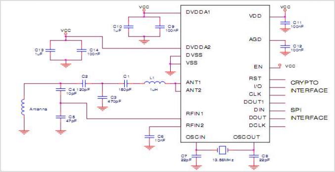
A very simple DIY crystal oscillator circuit that uses a quartz crystal for frequency stability and a suitable RF transistor. It employs a second or third harmonic crystal for operation. This DIY crystal oscillator circuit is designed to generate stable...