
cellular phone calling detector circuit schematic

The circuit operates on the principle of electromagnetic induction, where the sensor coil L1 picks up the electromagnetic waves generated by the cellular phone when a call is received. The coil is tuned to the specific frequency range of the phone's signal, ensuring optimal sensitivity and responsiveness to incoming calls.
Upon detection of the electromagnetic field, the circuit activates a light-emitting diode (LED) to provide a visual indication of the incoming call. The LED flashes at a rate that can be adjusted based on the circuit design, allowing for customization of the visual alert.
Key components of the circuit include the sensor coil L1, which is typically constructed using insulated copper wire wound around a non-conductive core. The circuit may also incorporate a transistor or operational amplifier to amplify the signal from the coil, ensuring reliable detection of the phone's electromagnetic emissions. Additionally, resistors and capacitors may be used to filter noise and stabilize the circuit operation.
Power for the circuit can be supplied by a small battery or a USB power source, depending on the design requirements. The compact size of the circuit allows for easy integration into various environments, making it a versatile solution for users who may need a discreet alert system for incoming calls.
Overall, this circuit provides an effective solution for alerting users to incoming calls without relying on the traditional ringer of a cellular phone, enhancing usability in situations where sound notifications may be impractical.This circuit was designed to detect when a call is incoming in a cellular phone (even when the calling tone of the device is switched-off) by means of a flashing LED. The device must be placed a few centimeters from the cellular phone, so its sensor coil L1 can detect the field emitted by the phone receiver during an incoming call..
🔗 External reference
Related Circuits
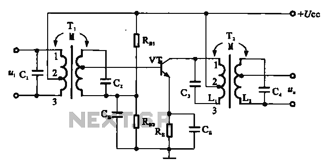
There are two resonant circuits in a double-tuned amplifier circuit, which consists of transformers T1 and T2 with primary and secondary coils that include parallel resonance capacitors. This circuit exhibits a resonance function and can be classified based on...
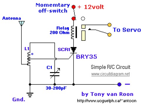
The diagram illustrates a straightforward and efficient receiver designed for activating garage doors, starter motors, alarms, warning systems, and various other applications. The silicon-controlled rectifier (SCR) utilized in this circuit features an exceptionally low trigger current of 30 µA,...
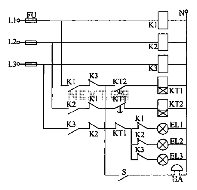
Any power supply and distribution sector should include phase sequence detection to ensure that the power supply phase sequence remains stable and unchanged. Additionally, any irreversible electromechanical product should also incorporate phase sequence detection to verify the phase sequence...
This circuit utilizes a 1458 dual op-amp to create a radar detector. C1 serves as the radar signal detector. The first op-amp functions as a current-to-voltage converter, while the second op-amp buffers the output to drive the piezo transducer....
High-quality, discrete component design for input and tone control modules to complement the 60-watt MOSFET audio amplifier with a high-quality preamplifier design. The circuit design focuses on creating a high-fidelity audio preamplifier that enhances the performance of a 60-watt MOSFET...
AVC - The circuit regulates the volume line automatically, providing an output voltage of approximately 4 volts peak to peak. This voltage remains consistent. The Automatic Volume Control (AVC) circuit is designed to manage audio levels dynamically, ensuring a stable...