
clock driver for sparkfun easydriver breakout

The EasyDriver stepper motor driver facilitates the control of stepper motors by translating digital signals into precise motor movements. In this project, the driver is powered by a DC voltage range of 7-30V, allowing for flexibility in power supply selection. The connection of the stepper motor to the driver is straightforward, with terminals A and B designated for the motor phases. Each transition from LOW to HIGH on the STEP pin results in a single step of the motor, enabling precise control over its movement.
The direction of rotation is manipulated via the DIR pin, which can be set to either a HIGH (+5V) or LOW (ground) state. The MS1 and MS2 pins are critical for defining the step resolution, which influences the precision of the motor's movement. The default configuration of eight-step resolution is suitable for many applications, but the ability to alter these settings via grounding the MS1 and MS2 pins allows for customization based on specific requirements.
The integration of a DIP switch enhances user interaction, enabling the selection of step resolution and maintaining a constant speed of one revolution per minute regardless of the chosen resolution. This is achieved through the microcontroller's programming, which adjusts timer settings based on the DIP switch input. An LED indicator provides visual feedback for each step taken by the motor, enhancing the usability of the circuit.
The AtTiny25 microcontroller serves as the brain of the operation, with its clock driven by a low-frequency watch crystal. This choice of clock source is crucial for the timing accuracy of the stepper motor control. The code implemented utilizes Timer 0 in output compare mode, allowing for precise timing of the step signals. The adjustments made to the OCR0A register based on the DIP switch settings ensure that the motor operates at the desired speed and resolution.
In summary, this project exemplifies the effective use of an EasyDriver stepper motor driver in conjunction with an AtTiny25 microcontroller to achieve precise motor control. The incorporation of user-selectable features and visual indicators enhances the functionality and user experience of the circuit.This is a project I`ve done on behalf of a person on an internet forum. The requested operation is simple: Use an EasyDriver stepper motor driver and a 1. 8 deg/rotation stepper motor and make the motor turn one revolution per minute. This frees me up a bit not having to select and source products myself, nor having to implement the actual stepper driver myself. The EasyDriver is REALLY simple in operation. Connect 7-30v DC to M+ (and ground to GND), connect a stepper motor to A and B and the motor automatically steps once for each LOW->HIGH transition on STEP. The direction is dependent on the state of DIR (+5v or ground). MS1 and MS2 together defines the step resolution. The driver chip is a Allegro A3967SLB, so the truth table for MS pins can be found in it`s datasheet, page 2.
The breakout board has pull-up resistors on both MS1 and MS2, which puts it in eight-step resolution as standard. To alter MS1 and MS2 you simply pull them to ground individually based on your desired resolution. I decided to make a few improvements to the requested operation. Via a DIP-switch the user can select the resolution for the EasyDriver while simultaneously altering the steps/minute so it will always make one turn per minute even though the step resolution is changed.
There is also an LED to indicate each step. I used a four-way DIP switch, the two remaining switches I used for step direction and to simply turn the steps on or off. The DIR signal is pulled up to +5v by a 10k resistor My circuit is built on a strip board and is based on an AtTiny25.
It`s system clock is driven by a low frequency 32. 768kHz watch crystal. It`s important to program the correct fuse bits for low frequency crystal oscillators! On to the code. I`m using Timer 0 with system clock as clock source in output compare mode. The registers defining when an output compare interrupt hits is altered based on MS1 and MS2 signals on the DIP-switch. #include #include #define F_CPU 8000000UL #include #define DIV64 3 #define DIV8 2 #define FULL !(PINB & (1<#define HALF !(PINB & (1<#define QUARTER (PINB & (1<#define EIGHT (PINB & (1< //MS1 pin 7 PB2 //MS2 pin 6 PB1 void step (void) { PORTB = (1<} ISR(TIMER0_COMPA_vect) //Timer/Counter0 Overflow interrupt routine { step(); } int main (void) { uint8_t previous = 1; uint8_t current = (PINB & 36); //Port configuration DDRB |= (1< PORTB |= (1< //Timer initialization TCCR0A |= (1< TCCR0B = DIV64; //Timer/Counter0 prescaler TIMSK |= (1< OCR0A = 76; /* OCR0A values 300ms period (ordinary step) =76/div64 150ms period (half step) 37/div64 75ms period (quarter step) 18/div64 37.
5ms period (eight step) 76/div8 */ sei(); //Enable interrupts globally while(1) { current = (PINB & 3); if (current != previous) { if (FULL) { OCR0A=76; TCCR0B=DIV64; } else if (HALF) { OCR0A=37; TCCR0B=DIV64; } else if (QUARTER) { OCR0A=18; TCCR0B=DIV64; } else if (EIGHT) { OCR0A=76; TCCR0B=DIV8; } previous = current; } } return 0; } 🔗 External reference
Related Circuits
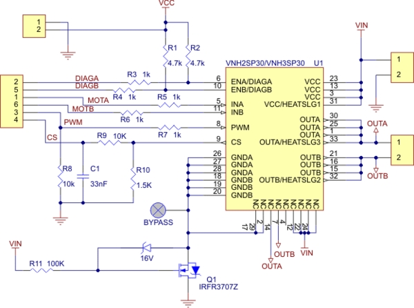
Need more current? If you have a larger motor ready for use, the Pololu High Current Motor Driver Board 14A 6V-16V is the ideal solution. Connect three digital lines to your microcontroller (five if error condition feedback is desired),...
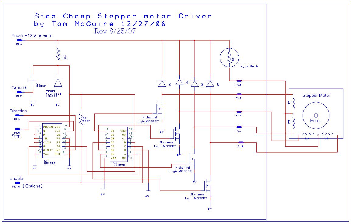
This circuit is designed to work with a variety of stepper motors, specifically 5 or 6 wire unipolar types. It operates within a voltage range of approximately 9 volts to 24 volts. A breadboard layout of the circuit is...
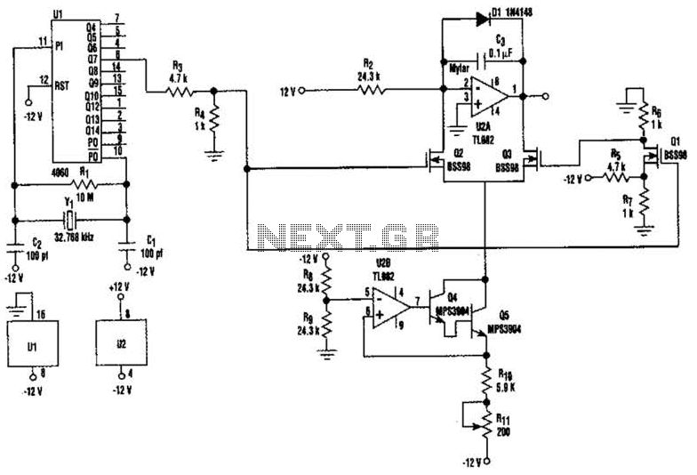
U2-a, U3, and R2 function as an integrator. Q2 and Q3 are alternately switched at 256 cycles. U2-b, Q4, Q5, and R8 through R11 form a constant current generator, with R11 configured to produce a symmetrical triangular waveform. The circuit...
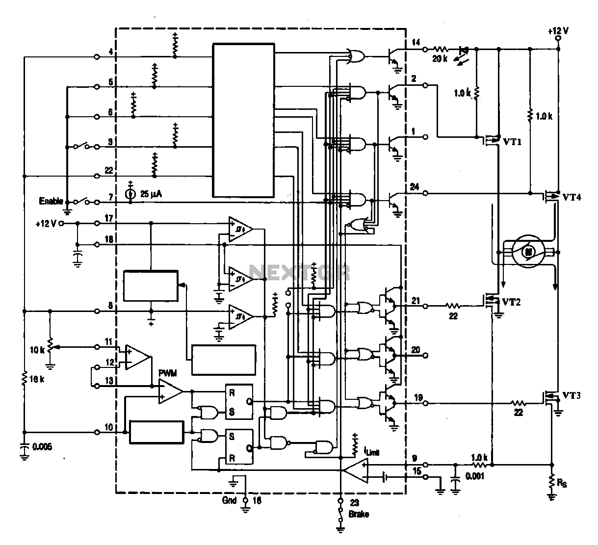
A DC brush motor driver circuit diagram utilizing the MC33035 chip is presented, illustrating a typical configuration for driving a straight DC brush motor. The circuit incorporates a field-effect transistor (FET) bridge driver setup. When transistor VT3 is activated,...
A clock utilizing numeric neon lamps, commonly referred to as nixies. These display devices were prevalent during the 1960s and 1970s, but their usage declined with the advent of LED displays. Today, nixies have become sought-after collectibles and are...
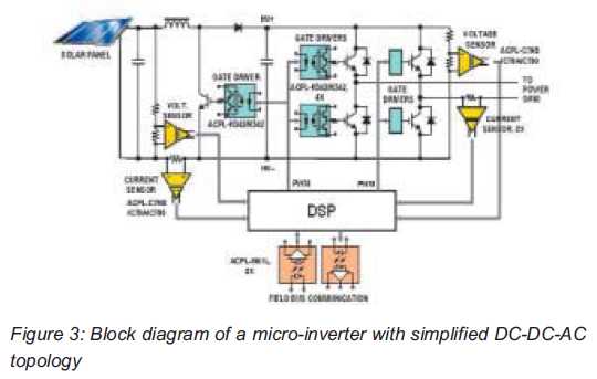
Both help improve efficiency and protect micro-inverters in photovoltaic (PV) solar applications. In 2009, the residential solar photovoltaic (PV) inverter market represented 90 percent of the total PV. The integration of micro-inverters in photovoltaic solar applications has significantly enhanced system...