
Closed loop speed control

The described circuit represents a sophisticated control system for a DC motor-generator setup, employing the UC3637 integrated circuit, which is specifically designed for motor control applications. The closed-loop control mechanism enables precise regulation of the motor speed by continuously comparing the actual speed with a desired speed setpoint.
The system begins with a tachometer that generates a voltage signal proportional to the motor's rotational speed. This voltage signal is then filtered to eliminate noise and ensure stability in the control loop. The filtered signal is fed into a speed command voltage comparator, which compares it against a reference voltage that represents the desired speed. Any deviation between the actual speed and the desired speed generates an error signal.
This error signal is processed by the internal differential amplifier of the UC3637, which amplifies the error to produce a suitable control voltage. This control voltage is crucial for adjusting the operation of the H-bridge, which is the core of the power amplification stage. The H-bridge configuration allows for bidirectional control of the DC motor, enabling it to run forwards or backwards as required.
The H-bridge is constructed using four MOSFETs, which are selected for their fast switching capabilities and efficiency. This arrangement not only facilitates rapid changes in motor direction but also optimizes power delivery to the motor, enabling smooth acceleration and deceleration.
The system is designed to achieve an acceleration rate of approximately 100 RPM every millisecond, indicating a highly responsive control loop. With a bandwidth of 80 Hz, the control system can effectively respond to changes in load and speed, ensuring that the motor operates within its desired parameters under varying conditions.
Overall, this DC motor-generator speed control circuit exemplifies advanced engineering principles in motor control, combining high-speed response, efficiency, and precision through the integration of modern electronic components.DC motor-generator speed closed loop control utilizing UC3637 internal error differential amplifier EA, after tachometer generator speed voltage signal is filtered with the spe ed command electrical voltage comparator after the error correction and amplified as a control voltage n. UC3637 the AOUT and B. Ut supply H-bridge switching power amplifier, which is composed of four MOSFET. The acceleration system approximately every millisecond iOOr/min. 3dB bandwidth of 80Hz.
Related Circuits
The L29 Stepper Motor Controller IC facilitates the control of four drive signals for two bipolar and four unipolar footfall motors in a microcomputer-controlled appliance. It allows for motor operation in half-step, full-step, and wave drive modes, utilizing switch-mode...
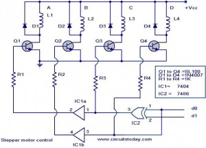
The following circuit illustrates a Stepper Motor Controller Circuit Diagram. This circuit is based on the 7404 IC. Features include a simple stepper motor. The stepper motor controller circuit utilizing the 7404 IC is designed to drive a stepper motor...

Tutorials, reviews, and software regarding airsoft. This project illustrates how to connect a PC to a small FRS radio via a simple RS-232 interface. There are several reasons for this connection. This project focuses on establishing a communication link between...
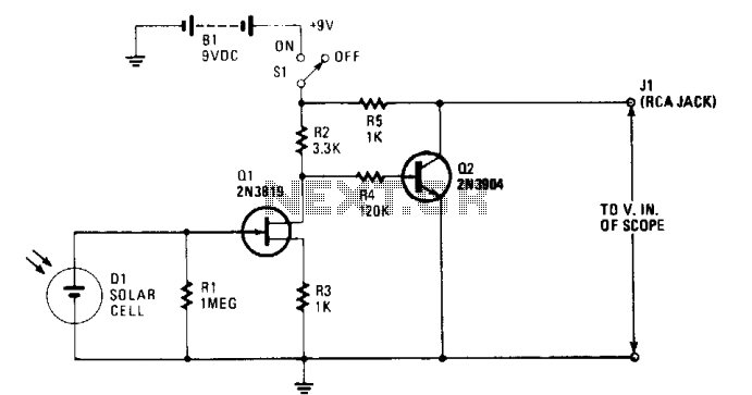
The solar cell is connected to the input of the field-effect transistor (FET), Q1, allowing it to generate a positive DC voltage at the gate when illuminated by light through the open shutter. This illumination reduces the negative gate-source...
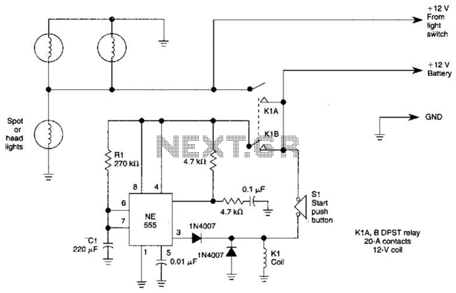
Pressing the START pushbutton activates either the headlights or spotlights for a specified duration. After 1 minute, determined by R1 and C1, the lights will turn off as the NE555 timer completes its cycle. The circuit utilizes a NE555 timer...
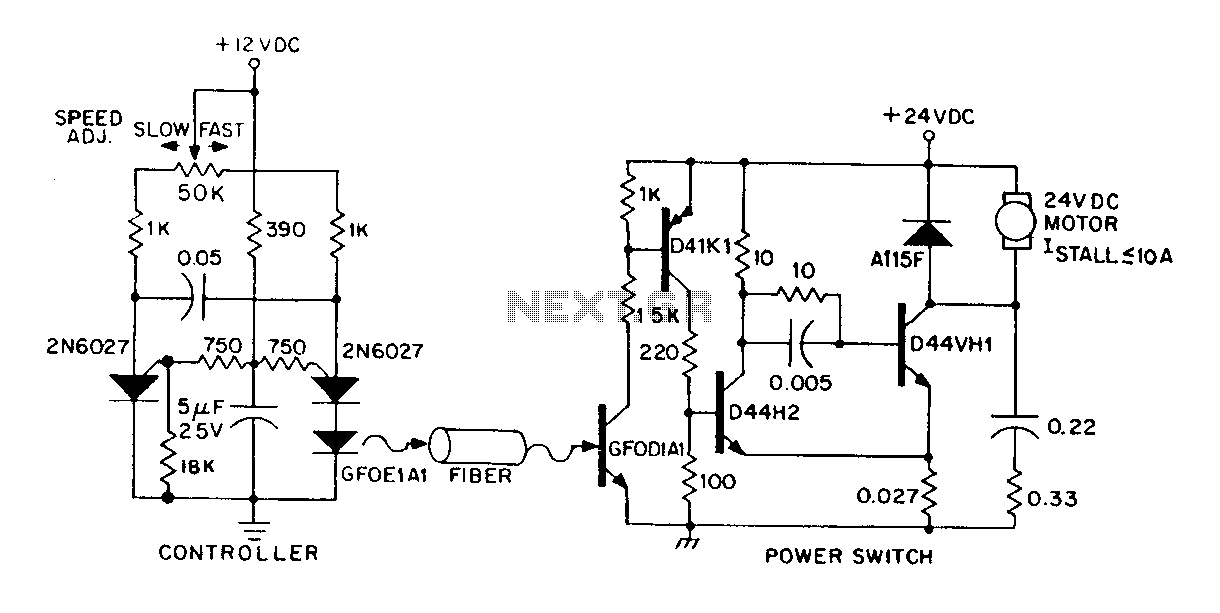
A DC power supply can be controlled through an optical fiber. The circuit includes a small DC motor (1/12 hp) that offers an isolated speed control channel. The control logic operates as an independent module, consuming 300 mW of...