
Color Sensor Circuit With CD4073 IC

The color sensor circuit typically employs a light-sensitive component, such as a photodiode or phototransistor, to detect and differentiate colors based on the wavelength of light. The circuit may include an RGB (Red, Green, Blue) sensor, which is capable of measuring the intensity of each primary color in the light spectrum.
In a standard configuration, the RGB sensor outputs three analog voltage levels corresponding to the intensity of red, green, and blue light. These outputs are then fed into an analog-to-digital converter (ADC), which translates the analog signals into digital values for further processing.
The microcontroller, often the central processing unit of the circuit, interprets these digital values to determine the color of the detected object. It can be programmed to respond to specific colors, triggering actions such as lighting up an LED of the corresponding color, activating a motor, or sending data to a display.
Power supply considerations are crucial in this circuit. A regulated voltage source is typically required to ensure stable operation of the sensor and the microcontroller. Additionally, bypass capacitors may be included near the power pins of the components to filter out noise and ensure reliable performance.
Overall, this color sensor circuit integrates optical sensing with digital processing, allowing for versatile applications in robotics, automation, and interactive systems.This circuit shows a color sensor circuit diagram. The circuit is based on the fundamentals of optics and digital electronics. This circuit will .. 🔗 External reference
Related Circuits
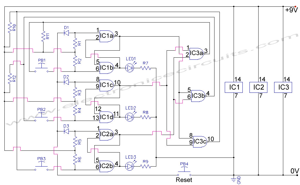
First Response Monitor, Input Selector, Game Circuit. This circuit is utilized for first response applications as it aids in monitoring various responses in games. The First Response Monitor circuit is designed to facilitate real-time monitoring and selection of input signals...
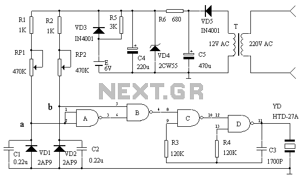
This lie detector circuit diagram provides two readings: one for challenging questions directed at the subject and another to display the subject's emotional state in general. The emotional states are detected not only by heart rate variations and perspiration...

This is a circuit for an accelerometer amplifier. It is a straightforward circuit. A precision accelerometer requires an inverting mode amplifier since these devices typically output charge. This amplifier converts charges into a voltage output. The circuit presented below...
This circuit serves as an over-temperature alarm and cooling system utilizing CD4011 four NAND gate integrated circuits to monitor the oven's temperature. In the event of a thermostat circuit failure or power outage, if the internal temperature exceeds or...
This high voltage converter circuit operates from a 30-volt power supply and can output a voltage ranging from 0 to 3 kV in version 1 or from 0 to 10 kV in version 2. The high voltage converter circuit is...

This circuit is designed for an electrically operated rolling shutter, typically featuring a standard control panel with a three-position switch: up, down, and stop. To automate the opening and closing with a time-controlled switch, additional wiring connections are required....