
High Voltage Converter Circuit

The high voltage converter circuit is designed to efficiently step up the input voltage from a standard 30-volt power supply to significantly higher output levels, specifically 0 to 3 kV for version 1 and 0 to 10 kV for version 2. The circuit typically employs a transformer-based architecture or a switched-mode power supply (SMPS) topology to achieve this voltage conversion.
In version 1, the output voltage is regulated using a feedback mechanism that monitors the output and adjusts the duty cycle of the switching element, ensuring stable operation across varying load conditions. The transformer in this version is designed to handle high voltages and is insulated appropriately to prevent arcing or breakdown.
Version 2, capable of delivering up to 10 kV, may utilize a more robust transformer with enhanced insulation and possibly additional stages of voltage multiplication to achieve the higher output. Safety features are critical in this version, including over-voltage protection, current limiting, and thermal shutdown mechanisms to prevent damage to the circuit or connected loads.
The circuit may also incorporate additional components such as high-voltage capacitors, diodes rated for high voltage, and adequate filtering to smooth the output voltage and reduce ripple. Proper layout and grounding techniques are essential to minimize electromagnetic interference (EMI) and ensure the safety and reliability of the high voltage output.
This converter circuit finds applications in various fields, including industrial equipment, scientific research, and medical devices, where high voltage is required for specific processes such as particle acceleration, x-ray generation, or electrostatic applications.Starting from a 30 volt power supply this high voltage converter circuit can deliver a voltage between 0 to 3 kV (version 1) or from 0 to 10 kV (version 2).. 🔗 External reference
Related Circuits

The SLB0586A integrated circuit from Siemens can be utilized to construct a straightforward touch light dimmer circuit, enabling the adjustment of lamp intensity. When paired with a TIC206D triac, this setup allows for smooth regulation of light intensity for...
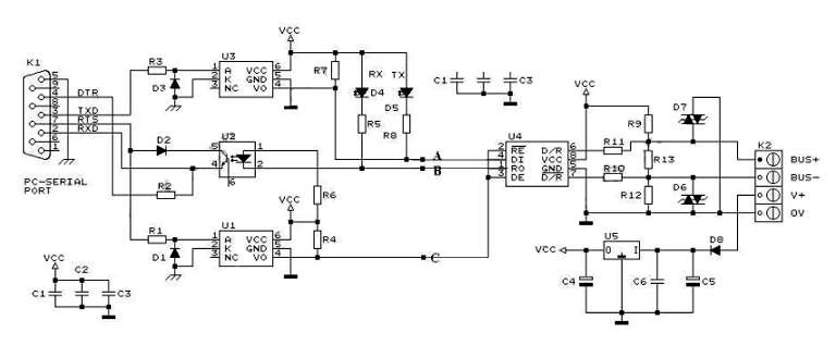
RS232 to RS485 Converter Circuit Schematic. RS232 to RS485 converters are primarily utilized in industrial and commercial settings. The RS232 to RS485 converter circuit is designed to facilitate communication between devices using different serial communication standards. RS232 is commonly found...
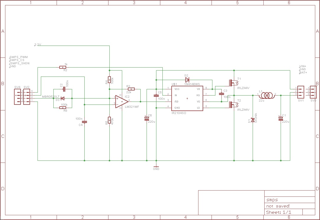
The circuit receives an input voltage (Vin), which is processed through a Switch Mode Power Supply (SMPS) utilizing two MOSFETs driven by an IR2104 driver. The output is directed to the battery positive terminal (Bat+). An LM321 operates as...
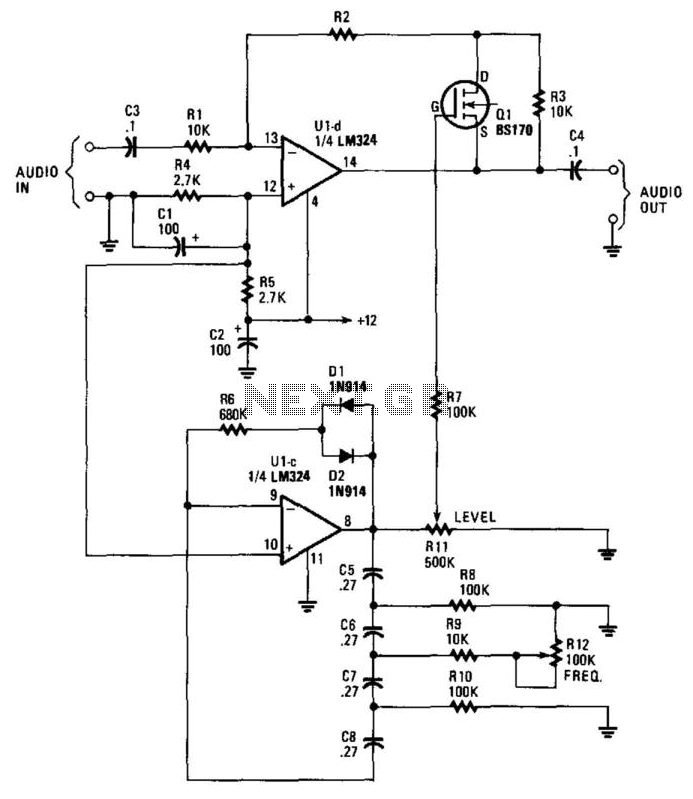
This circuit incorporates a Very Low Frequency (VLF) Amplitude Modulation (AM) component into an audio signal. This effect is commonly utilized in musical instruments. U1C, a phase-shift oscillator functioning at a few Hertz, generates a signal that modulates the...
Powered by a solar panel, the circuit provides a 5V pure regulated DC voltage. It consists of an oscillator transistor and a regulator transistor. The solar panel charges the battery when sunlight is sufficient to generate a voltage above...
The following article is a continuation of the application note titled "Defining and Testing Dynamic Parameters in High-Speed ADCs, Part 1." It outlines the test conditions and setup recommendations necessary for effectively measuring the dynamic performance parameters of high-speed...