
transducer current limiter circuit

To effectively drive an ultrasonic transducer while ensuring its protection, a driver circuit must be designed with a current limiting feature. The circuit typically includes a power source capable of delivering the required voltage and current, along with a suitable driver stage that can handle high-frequency signals.
A common approach to limit the output current involves the use of a current sensing resistor in series with the transducer. This resistor allows for the measurement of the current flowing through the circuit. The voltage drop across this resistor is proportional to the current, and it can be monitored using an operational amplifier configured as a comparator. When the current exceeds a predefined threshold, the comparator output can trigger a control mechanism, such as a transistor or a relay, to reduce the drive signal or shut off the output to prevent damage to the transducer.
In addition to the current limiting feature, it is crucial to consider the voltage ratings. For the specified ring transducer, the driver circuit should be able to handle input voltages up to 1,650V, while ensuring that the output power remains within safe limits. The circuit design should incorporate high-voltage components capable of withstanding these conditions without failure.
Thermal management is another critical aspect. Since the transducer can become damaged if the temperature exceeds 120°C, a thermal cutoff or sensor may be integrated into the circuit to monitor the temperature. If it approaches the critical threshold, the circuit can be designed to reduce the output power or shut down entirely.
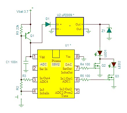
Lastly, the applications for this ultrasonic driver circuit are diverse, ranging from industrial cleaning processes to biomedical applications. Each application may have specific requirements for frequency, power, and control, which should be taken into account during the design phase to ensure optimal performance and reliability.Drive an ultrasonic transducer by using this driver circuit. I have a quesiton for this operation. How can I limit my output current I am using a 60W transducer and maybe it can be damaged because of the output current. Could you direct me, or share sample to add this limiter circuit Applications: High-power ultrasonic applications such as ultrasonic cleaning tanks,
ultrasonic plastic welding, ground sonar transducer, Bio Diesel mixer transducer, Solid separation transducer, stop organism growth on boat hull, Biodiesel mixing transducer, High-Torque Traveling Wave Ultrasonic Motor and others. Notes: For the thickness of the ring transducer used (5. 5mm), the maximum input voltage is 1, 650V but the power output should not exceed 70W for single transducer or 50W for parallel setup.
If the temperature is higher than 120C the transducer will depolarize and maybe fracture. So the operating voltage suggested is between 450-500V. 🔗 External reference
Related Circuits
CocaCola clearly stated that his circuit did not work correctly; the series was only complete when both LEDs were enabled, not otherwise. The circuit in question appears to involve a series configuration of light-emitting diodes (LEDs) that require both components...

A simple transistor amplifier circuit diagram and schematic that can be used as a 12-watt audio transistor amplifier. An operational amplifier (op-amp) integrated circuit (IC) is used to produce the required gain. This circuit is designed to amplify audio signals,...
The hum noise is produced by an electronic device with improper design. To address this issue, it is essential to identify the source of the hum. This involves checking the grounding, cabling, casing, and other factors that may contribute...
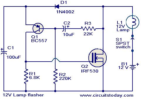
This circuit is a straightforward yet effective solution for flashing 12V lamps, particularly those utilized in automobiles. The flashing mechanism relies on transistor Q1 (BC557) and MOSFET Q2 (IRF530), with Q2 delivering the required drive for the lamp. The...
This sound wattmeter utilizes a series of colored LEDs as a scale to display the relative power output of an amplifier in watts. It is designed for easy integration into a speaker box, requiring only a connection to a...
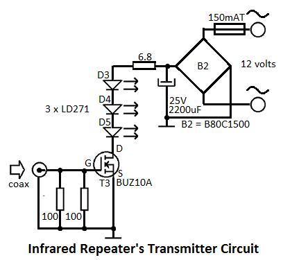
This infrared repeater system is utilized to extend the range of an infrared transmitter used with audio or video equipment up to 10 meters. The original signal is approximately. The infrared repeater system operates by receiving infrared signals from a...