
Common ground for different voltages in relay circuit

To achieve the control of a 12 VDC device using a microcontroller and a relay card, a circuit design must incorporate several key components. The microcontroller, which serves as the control unit, will send a signal to activate or deactivate the relay. The relay acts as an electrically operated switch that can handle the higher voltage and current needed to power the 12 VDC device.
The circuit typically consists of the following components:
1. **Microcontroller**: This device generates the control signal. Common choices include Arduino, PIC, or STM32 microcontrollers. The microcontroller's output pin is connected to the relay module's input pin.
2. **Relay Module**: The relay module consists of one or more relays capable of handling the 12 VDC load. It usually includes an opto-isolator for safety and to protect the microcontroller from back EMF generated by the relay coil. The relay coil requires a 12 VDC supply for operation, which can be provided from the same power source as the device being controlled or from a separate regulated power supply.
3. **Power Supply**: A 12 VDC power supply is necessary to power both the relay and the connected device. This power supply should be capable of providing sufficient current to meet the demands of the device being controlled.
4. **Protection Diode**: A flyback diode should be placed across the relay coil terminals to prevent voltage spikes (back EMF) when the relay is deactivated. This diode ensures that the current generated by the collapsing magnetic field does not damage the microcontroller.
5. **Control Circuit**: The microcontroller's output pin is connected to the input of the relay module, which may include a transistor to amplify the control signal. When the microcontroller sends a high signal, the transistor turns on, energizing the relay coil and closing the switch, allowing current to flow to the 12 VDC device.
6. **Load**: The 12 VDC device that needs to be controlled. When the relay is activated, the device receives power and operates as intended.
The circuit can be designed on a breadboard for prototyping or laid out on a printed circuit board (PCB) for a more permanent solution. Proper attention should be given to the layout to minimize noise and interference, especially if the microcontroller operates at lower voltages. Additionally, the relay's specifications should match the requirements of the load to ensure reliable operation.
In conclusion, this setup allows for effective control of a 12 VDC device using a microcontroller through a relay, enabling automation and remote control capabilities in various applications.Hello, My goal is to control a 12 VDC device (on/off) from a microcontroller using a relay card. The relay needs 12 VDC operating power (I use the.. 🔗 External reference
Related Circuits
A Variable DC Power Supply is an essential tool for electronics hobbyists. This circuit is not entirely new, but it is simple, reliable, robust, and short-proof, offering variable voltage up to 24V and variable current limiting up to 2A....
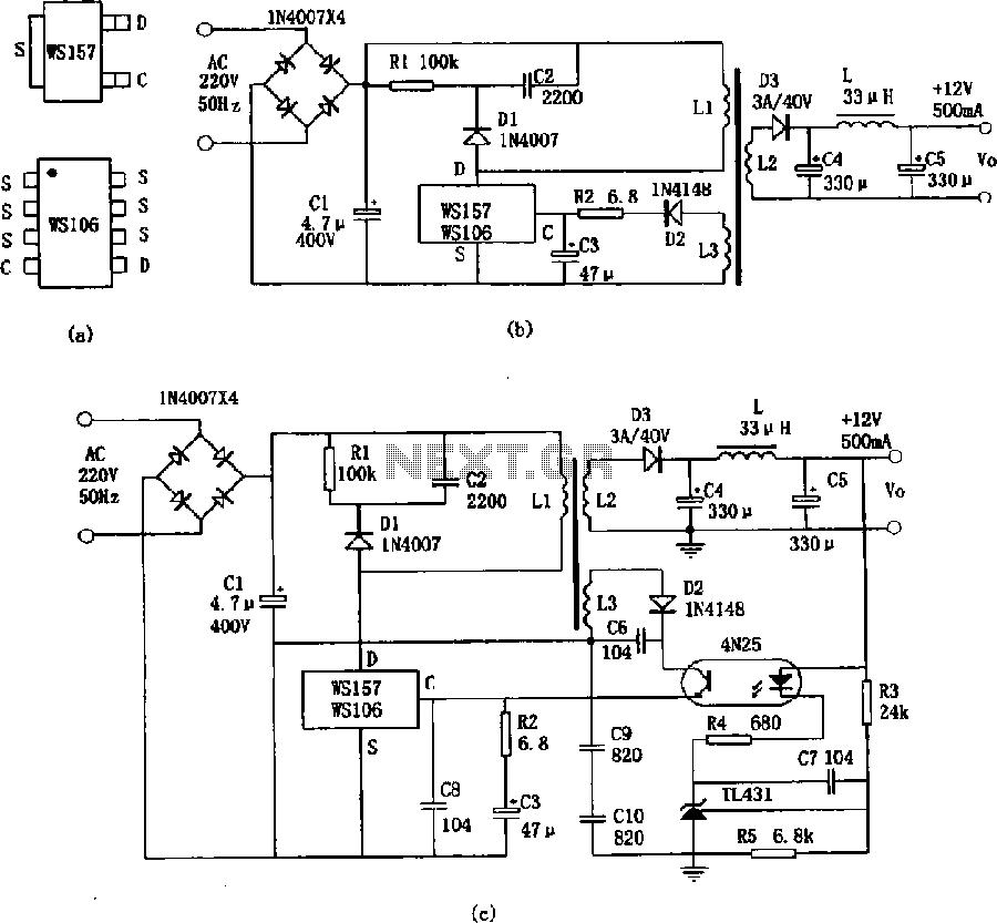
The WS157 or WS106 is a low-power miniature switching power supply that has been developed in recent years. It functions as a regulated switching power supply control device, featuring integrated internal control circuitry and power switches on a single...
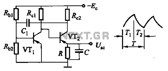
Common non-sinusoidal oscillator circuit, waveform and frequency formula - sawtooth oscillator - use multivibrator. The sawtooth oscillator is a type of non-sinusoidal waveform generator that produces a triangular or sawtooth-shaped output signal. This oscillator is commonly utilized in various applications,...
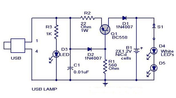
A simple USB-powered lamp designed to illuminate a desktop during power outages. The circuit operates at 5 volts sourced from a USB port. The 5V from the USB is directed through a current-limiting resistor (R2) and a transistor (Q1)....
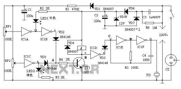
The alarm protection can trigger a sound and light alert when the mains voltage exceeds or falls below a predetermined threshold. It automatically disconnects the electrical power supply without damaging the electrical protection. The device is compact, fully featured,...
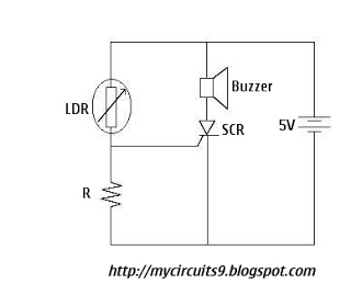
The Light Dependent Resistor (LDR) is a variable resistor whose resistance decreases as light intensity increases. Under normal light conditions, the resistance of the LDR is sufficiently high, resulting in an inadequate voltage across resistor R to activate the...