
Common Hot-Lead Regulator

The circuit in question is designed to efficiently convert the voltage from two AA batteries into a stable 5 V DC output. This is particularly significant as it can maintain functionality even when the batteries are nearing depletion, specifically at a voltage as low as 1.05 V per cell.
The efficiency of the circuit is approximately 80%, which is a crucial factor in battery-powered applications where maximizing battery life is essential. The output current capability of 4 mA at 5 V indicates that the circuit can power small electronic devices or sensors that require low power.
The heart of the circuit is an integrated circuit (IC) from Maxim Integrated Products, Inc., designated as IC1. This IC is likely a DC-DC boost converter, which is specifically designed to step up lower voltages to higher levels while maintaining efficiency. The boost converter operates by storing energy in an inductor and then releasing it to the output at a higher voltage, utilizing a switching mechanism to control the energy transfer.
The circuit's input stage will consist of the two AA batteries connected in series, providing a combined voltage of approximately 2.1 V when fully charged. The boost converter will then take this input and convert it to the desired output voltage of 5 V. The output current of 11 mA at the input stage suggests that the circuit may draw more current from the batteries than it outputs, which is typical in boost converter applications due to inherent losses and the need to store energy in the inductor.
Additional components that may be present in the circuit include input and output capacitors to stabilize the voltage, a diode to prevent reverse current flow, and possibly feedback resistors to regulate the output voltage accurately. The layout of the circuit should ensure minimal parasitic inductance and capacitance to maintain efficiency and performance.
In summary, this circuit is a practical solution for powering devices from low-voltage battery sources, demonstrating effective energy conversion while ensuring long operational life even as the battery voltage declines. The use of a dedicated IC from a reputable manufacturer further assures reliability and performance in various applications. This circuit derives 5 Vdc from 2-AA cells—even at their end-life voltages of 1.05 V, and is approximately 80% ef ficient, providing 5 V at 4 mA from 2.1 V at 11 mA. IC1 is manufactured by Maxim Integrated Products, Inc.
Related Circuits
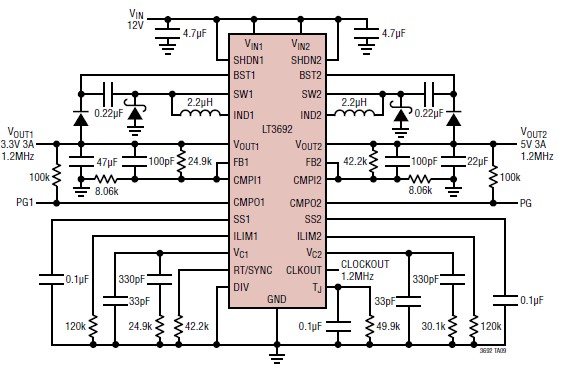
The LT3692 dual current mode PWM step-down DC-DC converter circuit, featuring two internal 3.5A switches, can be utilized to design a straightforward power supply circuit suitable for various electronic applications, including distributed supply regulations and automotive circuits. The LT3692...
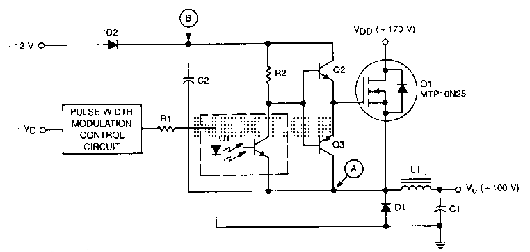
This circuit is essentially a classic buck regulator that utilizes a TMOS N-channel power FET for the chopper and generates its own supply for gate control. The unique feature of this circuit is its method for creating a separate...
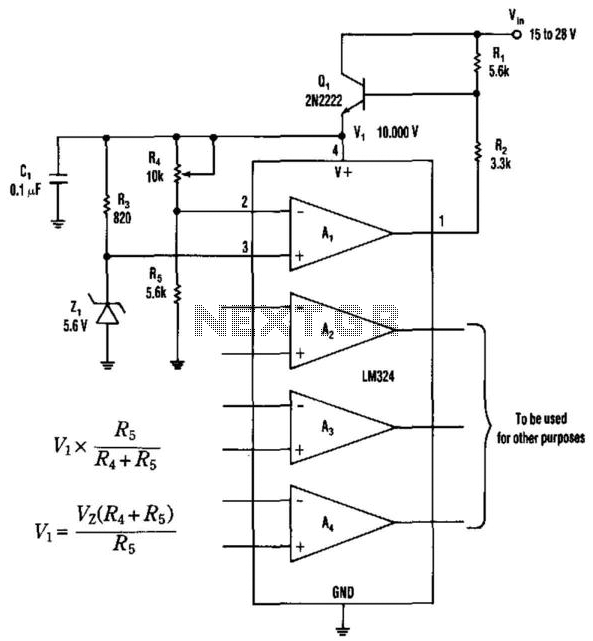
This operational amplifier provides a simple approach to creating a single-polarity stable voltage source. The transistor Q1 receives base drive through resistor R1 and conducts to generate a voltage (Vi) across the integrated circuit's supply pins. The operational amplifier...
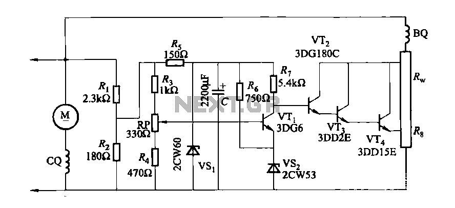
The DC generator automatic voltage regulator circuit is illustrated in Figure 7-53. This circuit is designed for a 40kW, 230V DC shunt complex machine, with a voltage change rate of up to 2.5 percent. In Figure 7-53, BQ represents...
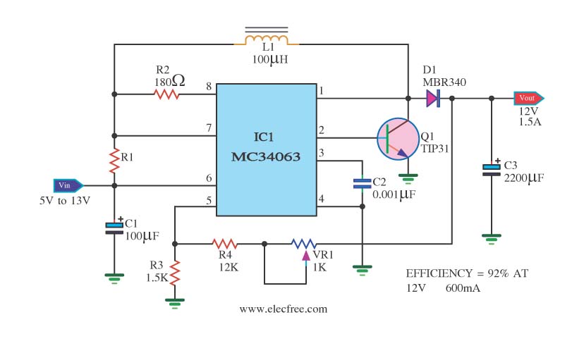
The circuit is a battery-powered voltage regulator that outputs 12V at 1.5A. It accepts an input voltage range from 5V to 13V. The circuit utilizes the MC34063 integrated circuit, making it a straightforward design. The circuit primarily functions as a...
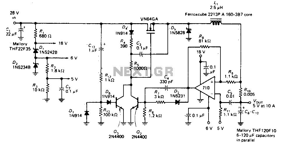
This circuit provides a regulated DC output with less than 100 mV of ripple for microprocessor applications. The required operating voltages are derived from a bleeder resistor network connected across the unregulated 28 V supply. The output of the...