
Compact DJ Station

General Circuit Diagram: All passive circuitry (controls, faders, switches, input and output connectors) is fully illustrated, while active amplification modules are represented by labeled triangle symbols.
Phono Amplifier Module: This high-gain stereo amplifier is designed for moving magnet pick-up cartridges, ensuring a frequency response that adheres to the RIAA equalization curve. It is based on the low-noise, low-distortion LS4558 dual IC, requiring two identical stereo modules of this type.
Headphone Amplifier Module: Previously available on this website as the Portable 9V Headphone Amplifier, this circuit features a low current drain stereo amplifier based on the low-distortion, low-noise 5532 dual IC. It can deliver 3.6V peak-to-peak into a 32 Ohm load at a 9V supply (corresponding to 50mW RMS) with less than 0.025% total harmonic distortion at 1kHz and 10kHz. The input source can be selected using SW1 for Channel 1 and SW2 for Channel 2. Moving magnet pick-ups should be connected to Phono 1 and 2 inputs, while CD players, iPods, tape recorders, PC audio outputs, and similar devices can connect to Line 1 and 2 inputs.
After separate level controls for each channel (P1 and P2), the incoming audio signals are mixed and cross-faded using P3 and an associated resistor network. The crossfader control allows both channels to be mixed at equal intensity when positioned in the middle. When P3 is fully rotated towards R3-R4, only the Channel 1 signal is present at the main output, muting Channel 2. Conversely, when P3 is rotated towards R1-R2, only the Channel 2 signal is present, muting Channel 1. This network leads to the Mixer Amplifier, followed by the Master Level control (P4) and the main output sockets.
A low-impedance microphone can be connected to the mic input. P6 controls the signal level after amplification by the microphone amplifier module and feeds the left and right mixer amplifiers through resistors R9 and R10, ensuring the speaker's voice is centered in the soundstage. A stereo headphone amplifier with cue gain control is included for monitoring purposes. The Cue Select switch (SW3) allows headphone monitoring of Channel 1, Channel 2, or the Master Channel, independently of the signal present at the main output.
J13 is a mini DC power socket designed for the plug of a 9V DC external supply adapter. Due to the low total current drain (approximately 13mA average), a 9V battery is also suitable for powering the entire station. For improved RIAA equalization, it is recommended to use low tolerance components for resistors R5, R6, R7, R14, R15, and R16 (1%-2%) and capacitors C3, C4, C8, and C9 (2%-5%).
This comprehensive DJ mixer circuit enables effective audio mixing and monitoring, making it suitable for portable DJ applications. Its modular design allows for easy troubleshooting and component replacement, ensuring reliability in various performance environments.This project consists of a small, portable DJ mixer powered by a 9V dc external supply adaptor or from a 9V PP3 battery. The mixer features two stereo phono inputs and two stereo line-level inputs and has one stereo mixing channel.
A microphone input and a stereo main output with adjustable gain are also provided. Headphone monitoring includes a c ue switch for selecting Channel 1, Channel 2 or Master Channel. For easy understanding, the circuit is divided into five blocks, as follows: General Circuit diagram:all passive circuitry (controls, faders, switches, input and output connectors) is shown in full, whereas active amplification modules are represented by suitably labeled triangle symbols. Phono Amplifier Module: a high gain stereo amplifier suitable for moving magnet pick-up cartridges, having a frequency response according to RIAA equalization curve and based on the low noise, low distortion LS4558 dual IC.
Two identical stereo modules of this type are required. Headphone Amplifier Module: this circuit was already present on this website under Portable 9V Headphone Amplifier. It features a low current drain stereo amplifier based on the low distortion, low noise 5532 dual IC, capable of delivering 3.
6V peak-to-peak into 32 Ohm load at 9V supply (corresponding to 50mW RMS) with less than 0. 025% total harmonic distortion (1kHz & 10kHz). The input source can be selected by means of SW1 for Channel 1 and SW2 for Channel 2. Moving magnet pick-ups must be connected to Phono 1 and 2 inputs, whereas CD players, iPods, Tape recorders, PC Audio outputs and the like can be connected to Line 1 and 2 inputs. After a separate Level control for each channel (P1 and P2), the two incoming audio signals are mixed and cross-faded by means of P3 and associated resistors network.
The Crossfader control mixes both Channels at the same intensity when set in the middle position. When the cursor of P3 is fully rotated towards R3-R4, only Channel 1 signal is present at the Main output, whereas Channel 2 is muted. Conversely, Channel 2 signal is present at the Main output and Channel 1 is muted when the cursor of P3 is fully rotated towards R1-R2.
This network is followed by the Mixer Amplifier, the Master Level P4 and the Main output sockets. A low impedance microphone can be connected to the Mic input. P6 controls the signal level after amplification by the Microphone Amplifier module and feeds the Left and Right Mixer Amplifiers through R9-R10. In this way, the speaker`s voice will be reproduced at the center of the soundstage. A stereo Headphone Amplifier with cue gain control is provided for monitoring purposes. The Cue Select switch SW3 will allow Headphone reproduction of Channel 1, Channel 2 or Master Channel, independently of the signal present at the Main Output.
J13 is a Mini DC Power Socket into which the suitable plug of a 9V dc external supply adaptor should be inserted. In any case, due to the low total current drain (about 13mA average), a 9V battery can be used satisfactorily to power the entire Station.
A more strict RIAA equalization curve will be obtained if low tolerance components are used for R5, R6, R7, R14, R15, R16 (1% - 2%) and C3, C4, C8, C9 (2% - 5%). 🔗 External reference
Related Circuits
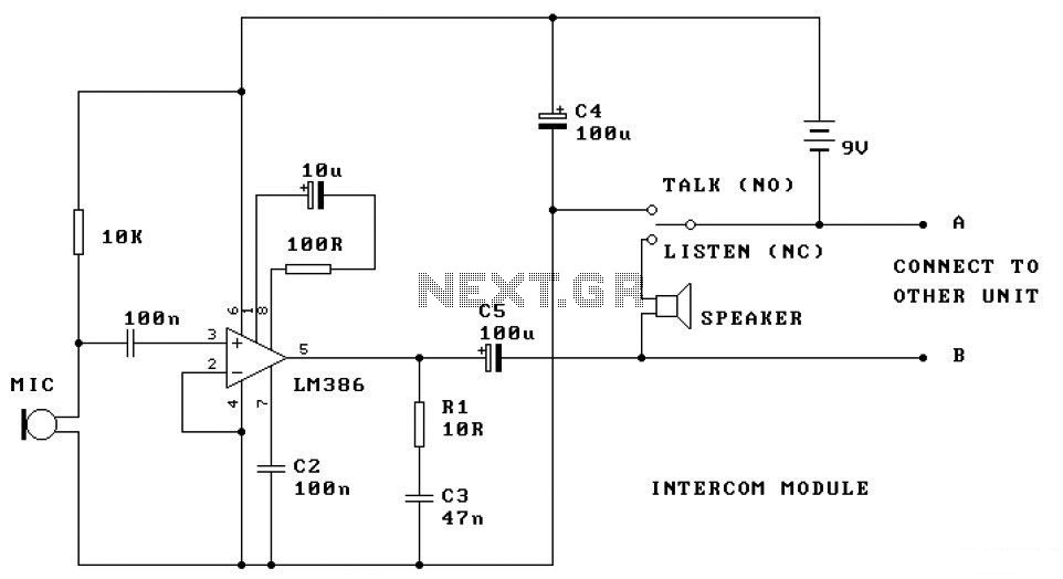
This is a two-station intercom system that operates using a pair of wires connecting each intercom unit. Each unit is self-contained, featuring its own battery, speaker, microphone, and amplifier circuit. An LM386 audio power amplifier is utilized in the...
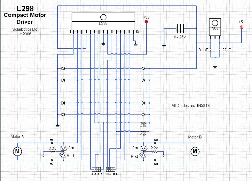
The ArduinoISP Bootloader/Programmer Combination Shield (not displayed) works with an Arduino equipped with a USB to serial chip (e.g., Arduino Uno) to upload the bootloader and sketches to a DIYduino. A USB to Serial programmer can also be utilized...
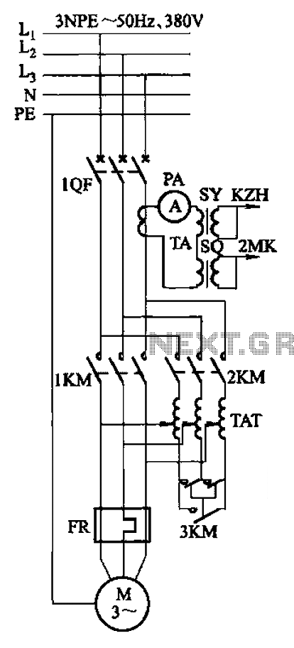
Autotransformer voltage starting, with an adjustable starting time of 30-60 seconds. It includes the SDJ electrode liquid level sensor of HJ-13 type, a pump control system box of HKD-21B type, 1MK level modules adopted by HKG-1SG type, 2MK start...
The magnetic field generated in the ballast collapses rapidly, resulting in a high voltage across the tube, which causes the internal gas to conduct. This process can be likened to gradually inflating a balloon and then puncturing it with...
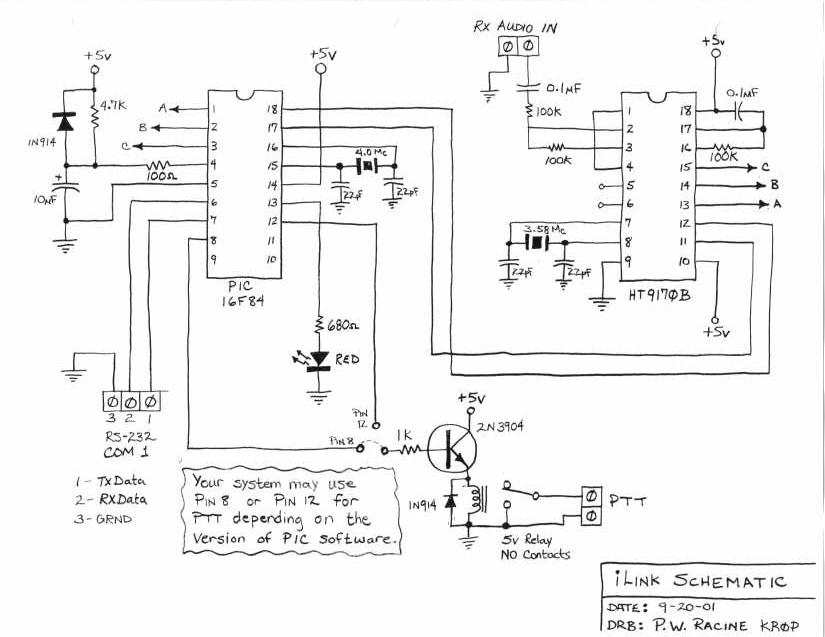
The following is a layout of a repeater system and the components required to operate it. The ILink system was designed by Graeme, M0CSH, and credit for its success goes to him. The circuit described is intended specifically for...
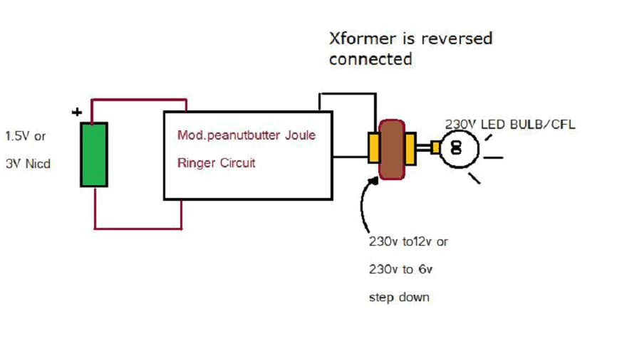
Various threads on ringer circuits have been observed, showcasing multiple variants, particularly concerning the types of transformers utilized, such as air core and step-down transformers. One notable circuit is the 12V-to-120V configuration, which employs a joule ringer that utilizes...