
KB0PS ILink Station

The repeater system described is an integration of multiple components that work together to facilitate seamless communication via the ILink protocol. The Hamtronics R301 VHF receiver is configured to operate at a specific frequency of 147.240 MHz, ensuring it captures the necessary signals for repeater activity. The incorporation of the Hamtronics TD-5 subaudible tone decoder is crucial, as it allows the system to respond only to relevant signals, filtering out unwanted noise and ensuring that the link receiver remains operational only during active communication.
The link transmitter, the Hamtronics T304 UHF transmitter, plays a pivotal role in relaying audio from the link receiver back to the repeater. This UHF link is strategically prioritized to allow for 2-meter activities to take precedence, ensuring that local communications are not interrupted by the link system. This design consideration is essential for maintaining operational integrity and user experience.
Construction of the ILink board emphasizes modularity and ease of access. The use of screw terminals simplifies the connection process, making it easier to test and modify the circuit without the need for soldering. The choice of perf board as the substrate allows for flexible layouts and easy alterations, which is particularly beneficial during the prototyping phase.
The design includes specialized components such as the EPROM and DTMF decoder ICs, which may require sourcing from specific suppliers. The programming of the EPROM is a critical step in the setup process, and the availability of PIC programmers provides options for customization and further development of the system. This comprehensive approach ensures that users can effectively link their repeaters to the ILink system while maintaining control over their communication infrastructure.The following is a layout of my repeater system and what was needed to get it on the air. The ILink system was designed by Graeme, M0CSH, and I take no credit for its success. The circuit below is only required by repeater control stations (sysops) and not by the average PC user of ILink. This information is only provided to help other amateurs li nk their repeater to the ILink system. The link receiver consists of a separate Hamtronics R301 VHF receiver with the Hamtronics TD-5 subaudible tone decoder. The VHF receiver is tuned to 147. 240 MHz and receives the repeater activity off-air. Whenever there is activity on the 147. 240 repeater COR, the repeater generates a 77 Hz subaudible tone which in turn un-mutes my link receiver.
The link transmitter consists of a separate hamtronics T304 UHF transmitter which sends link audio to the repeater via a UHF link. Whenever the link COR is active at the repeater, the 77 Hz subaudible tone is disabled to prevent a feedback loop into my link system.
The UHF link is voted at the repeater and its priority is set very low. This allows any 2 meter activity to override the link which in turn gives us full control of the link system. This is the layout of my iLink board. When building this board, I used screw terminals for all of my external connections. I find this dresses up the board nicely, and makes it very convenient when testing the circuit out; there is no need to solder and unsolder connections.
The circuit is build on perf board which was purchased from Radio Shack. A lot of my projects are down with perf board due to the time saved in laying out a board. Also, perf board is easy to work with if there is a time when I need to make a modification to the circuit. The ILink circuit was designed by Graeme, M0CSH. I drew up a schematic based on the original schematic obtained from Graeme, himself. As you can see, the ILink circuit consists of 2 main components, the EPROM and the DTMF Decoder IC`s.
Aside from these two components, which must be specially ordered, the remainder of the components are supplied by your neighborhood Radio Shack store. The largest hurdle to over come when building the ILink board is trying to figure out how to program the EPROM (PIC).
If you decided to build your own system, one of the tools you should purchase is a PIC programmer which could cost you about $65. 00. You also have the option to build your own PIC programmer, which still adds some aditional cost to the original project.
The other option is to order the pre-programmed PIC from Graeme, M0CSH. You will find more information on this at his website, AACNET MANAGEMENT. 🔗 External reference
Related Circuits
The timing interval is initiated by applying power and is determined by RT-CT. At the end of the interval, a unijunction transistor triggers a silicon-controlled rectifier to apply nearly the full supply voltage to the load. The delay range...
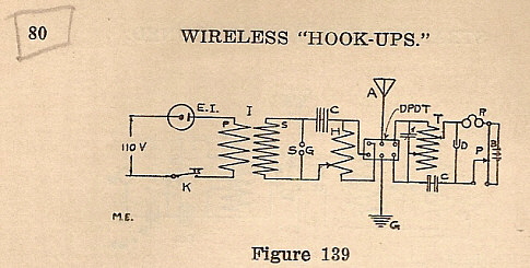
Dodd's 1909 receiver has survived and was discovered among various parts purchased at a yard sale. The components were identified from a photograph of the 1909 Station. Many of these parts were utilized in the construction of Dodd's 1912...
This article provides conversion instructions for radio model GE/MACOM MASTR-III Group 2 (150.8-174 MHz) Repeater or Base, Combination Number SXS, to enable it to operate effectively in the 144-148 MHz range. It is important to note that this document...
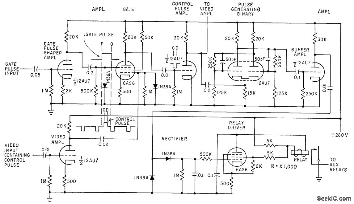
Control pulses transmitted during the blanking interval by a television network transmitter are decoded by receiver circuits and translated into six distinct switching actions. These actions are utilized to introduce special program content, such as commercials, weather reports, and...
A distribution substation is defined by the apparent power of the transformer and its configuration, which can be aerial, terrestrial, or underground. A distribution substation plays a critical role in the electrical power distribution network. It serves as a point where...
This 1-Wire MicroLAN uses a capacitor and diode half-wave rectifier to provide parasitic power from the data line for the station's various sensors and to transfer data. Each sensor has a unique serial number that identifies it to the...