
dark detector led ldr

This dark detector LED circuit operates on the principle of light intensity variation. The LDR, which exhibits a decrease in resistance with increasing light levels, plays a crucial role in detecting ambient light conditions. In darkness, the resistance of the LDR increases significantly, allowing the circuit to function as intended. The transistor 2N2222 is configured in a common-emitter arrangement, where it acts as a switch that controls the LED based on the voltage across the LDR.
The 50K variable resistor provides flexibility in adjusting the sensitivity of the circuit. By varying this resistor, the threshold light level at which the circuit activates can be finely tuned, enabling the LED to respond to different lighting environments. The inclusion of a 1K resistor serves to limit the current flowing through the LDR, preventing potential damage from excessive current when the variable resistor is set to its minimum resistance.
The 330-ohm resistor connected in series with the LED ensures that the current flowing through the LED is within safe operating limits, thus prolonging the life of the LED while maintaining adequate brightness. The choice of four 1.5V batteries for power supply offers versatility in terms of battery size and type, making the circuit suitable for various applications, such as night lights or automatic lighting systems in dark environments. Overall, this simple yet effective circuit design demonstrates fundamental principles of electronic components and their interactions in response to environmental changes.Here is a project of a simple dark detector LED circuit. In the previous topic we have discussed a light activated LED circuit. By simply changing the positions of the resistors and LDR we have converted the circuit in a dark detector LED or dark activated LED circuit. The circuit will light up an LED when it will detect no light. An LDR (Photores istor) is used in this circuit for sensing the light and dark conditions, and transistor 2N2222 is working as a switch. When the LDR will detect no light it will open the transistor 2N2222 due to which the LED will light up.
The 50K variable resistor (VR) is used to adjust the desired light condition on which the LED will light up and 1K resistor is used to protect the LDR from direct connecting to the supply when the 50K variable resistor is on zero. The 330 ohms resistor is used to provide the required current to the LED. The circuit can be operated with four 1. 5V batteries of any size. 🔗 External reference
Related Circuits
The metal detector circuit consists of a probe oscillator, a PLL (phase-locked loop) circuit, and an audio alarm circuit. The probe oscillator includes a detection coil (L), transistor (V1), and several resistors (R1 to R3) and capacitors (C1 to...
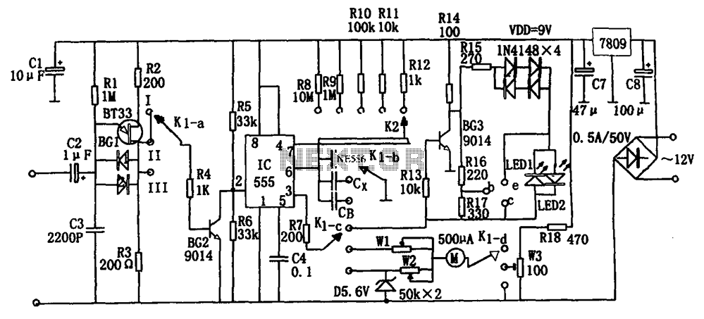
The frequency detection circuit utilizes a transistor line, adjustable via a preset switch K1, to convert capacitance and frequency measurements. The K1 switch is positioned to detect capacitance. The circuit comprises components including a 555 timer, resistors R8 to...
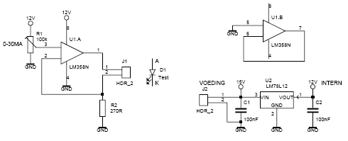
This led tester uses a power switched op-amp. The control range is about 0-30mA. Thus, all test and standard LEDs, the voltage across the LED to read. The power supply is an example lab power supply at least 15V,...
The LM3915 is a monolithic integrated circuit that senses analog voltage levels and drives ten LEDs providing a logarithmic 3 dB/step analog display. LED current drive is regulated and programmable, eliminating the need for current limiting resistors. More: This...

This circuit diagram represents a low-cost metal detector utilizing a single transistor circuit in conjunction with an old pocket radio. It operates as a Colpitts oscillator functioning within the medium band frequency range, with the radio tuned to the...

This high power led mood light is based on PIC16F628 and the ability of this mcu to produce PWM pulses. Varying pulse width we can produce millions of color combinations using only the three basic colors. So only one...