
Complete SS Laser Power Supply Schematics

The design of the power supplies for pulsed solid-state lasers involves several key components that work together to deliver the necessary energy for laser operation. The pulse forming network (PFN) plays a pivotal role in shaping the electrical pulse that drives the laser. The capacitor serves as the primary energy storage element, while the inductor influences the pulse duration and shape, which are critical for effective laser performance.
In the case of PFN1, the 36 µF capacitor is designed to handle high voltages, providing a significant energy reservoir. The choice of a non-electrolytic capacitor with low ESR is essential for minimizing energy losses during discharge, thereby maximizing the efficiency of the system. The inductor's value, determined through testing, ensures that the pulse duration is optimized for the specific laser application.
The automatic bleeder circuit included in the design is crucial for safety, as it prevents the capacitor from retaining a dangerous charge when the system is not in operation. This feature is particularly important in high-voltage applications where accidental contact could lead to severe injury or fatality.
When adapting these circuits for different types of solid-state lasers, careful consideration must be given to the specifications of the laser being driven. Adjustments to the capacitor and inductor values may be necessary to accommodate variations in energy requirements and pulse characteristics. The flexibility in design allows for a wide range of applications, from small-scale laboratory setups to larger industrial systems.
Safety precautions cannot be overstated in the context of working with high-voltage laser power supplies. Proper personal protective equipment (PPE) should be worn, and all safety protocols must be followed rigorously to mitigate risks associated with electrical hazards and laser emissions.This chapter contains circuit diagrams for several power supplies for pulsed solid state lasers. These include units suitable for driving the popular Hughes ruby and YAG rangefinder laser assemblies as well, one using the flash from a disposable pocket camera, and a high energy flashlamp power supply for that 8 inch long surplus NOVA laser rod you have been saving. :) The pulse forming network is what determines the performance of a pulsed solid state laser. Thus, there is a great deal of flexibility in the design of the capacitor charger and trigger circuits. Systems designed for other applications can often be adapted for solid state laser power supplies. See the chapter: SS Laser Power Supplies for more information. And the schematics in this chapter can be easily modified for larger, smaller, or different types of solid state lasers.
WARNING: All of these systems are potentially lethal - some just more lethal than others. Hey, but when you`re dead, it probably doesn`t matter how well done you are. Before even thinking about building or going near one of these systems, make sure you have thoroughly read, understand, and follow the laser and electrical safety guideline provided elsewhere in this document! PFN1 (manufacturer and model unidentified) is a combination of a 36 uF, 950 V energy storage capacitor, 0.
03 mH inductor, automatic bleeder circuit, and various connectors and other stuff. The capacitor is marked with its rating but the inductor is not and its value was determined by performing a `ring test` using both a separate high-Q 1 uF capacitor and then the one in the PFN. The original application for PFN1 was most likely to be used with the SSY1 laser head (see the section: A Small Nd:YAG Laser - SSY1 ).
The maximum useful energy into the flashlamp is around 14 to 15 J when charged to just over 900 V. Pulse Forming Network 1 shows the assembly with major components labeled. This unit is/was available from Meredith Instruments. When used without modification, the combination of the 36 uF capacitor and 0. 03 mH inductor will result in a 50 to 100 us pulse duration (dependent on other circuit parameters, probably closer to 100 us in practice). This is quite well matched to a Nd:YAG rod. With a well designed cavity, 15 J should be enough to threshold a 50 mm x 4 mm Nd:YAG rod (which is what it apparently was intended to pump) and considerably more than enough for a 25 mm rod.
Note that the capacitor in PFN1 is a very high quality non-electrolytic type. It may be a Polyester film capacitor with an ESR (Equivalent Series Resistance) of around 0. 02 Ohm (compared to almost 1 Ohm for a combination of electrolytic photoflash caps with the same uF and V ratings). The extremely low ESR is essential to achieve the required short pulse duration at reasonable efficiency (i.
e. , maximizing energy transfer to the flashlamp) or at all. Remove the other usable components from the PFN1 casting, unsolder the capacitor wire that goes through the base, and free up the other longer capacitor wire by breaking it free of the Epoxy globs fastening it in place and then tuck it out of the way so it won`t get damaged (e. g. , wrapped in a tight spiral on the end of the capacitor). Use a hack saw or rotary tool to slice the thin cast metal surrounding the capacitor just deep enough to reach the tough rubbery potting compound and no deeper.
This may have to be done in several places lengthwise, as well as around the base of the capacitor (next to where the other components were mounted). Then, carefully but persuasively pry the metal pieces from the potting compound leaving the capacitor stuck to the base.
It`s better to make some more cuts than to use a lot of force. It should be possible to peel the potting compound from the bottom of the capacitor but the adhesion there seems to be much stronger than to the yellow Mylar and it doesn`t look so bad left in place. :) This power sup 🔗 External reference
Related Circuits
The filter consisting of resistors R1, R2, and capacitor C1 integrates the PWM waveform. The purpose of the operational amplifier appears to be that of a non-inverting amplifier, with the gain determined by resistors R6 and R7. However, the...
The circuit illustrated relates to a standard industrial UPS (Uninterruptible Power Supply), demonstrating how the batteries assume control during an electrical outage. The Uninterruptible Power Supply (UPS) circuit typically consists of several key components that ensure a reliable power supply...
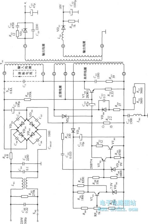
A high voltage switching stabilized voltage supply circuit is illustrated in the diagram. This is the switching power supply for an 80P type color television. It utilizes auto-excitation and a PWM circuit. The output is isolated from the power...
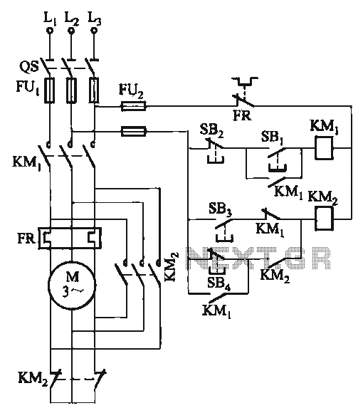
The C620 lathe Y-conversion includes a power-saving circuit designed for controlling the motor's reversing functionality. This system is applicable to machines such as the C620, C630, and CW61100A lathes, as well as radial drilling and milling machines. The C620 lathe...
Integrated circuits (ICs) have largely replaced traditional circuits like this one; however, this circuit is still utilized where the flexibility of a discrete device design is desirable. The components are readily available, and the issue of IC obsolescence is...
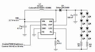
The schematic diagrams for the TPS61042 current LED driver illustrate its capability to power eight LEDs with an efficiency of 81% at 3.6V and 18.6mA. The TPS61042 is commonly utilized in applications such as white LED supply for backlight...