
Uninterruptible Power Supply (UPS): BasicCircuit
: BasicCircuit")
The Uninterruptible Power Supply (UPS) circuit typically consists of several key components that ensure a reliable power supply during interruptions. The core of the UPS is its battery system, which is responsible for providing backup power when the main electrical source fails.
In the circuit, the battery is connected to an inverter, which converts the stored DC power from the batteries into AC power, suitable for powering connected loads. The inverter is equipped with control circuitry that monitors the input voltage from the mains supply. When a power failure is detected, the control circuitry automatically switches the load from the mains supply to the inverter output.
Additionally, the UPS circuit includes a rectifier, which converts AC power from the mains into DC power to charge the batteries during normal operation. This ensures that the batteries remain charged and ready to provide power during an outage. A battery management system (BMS) may also be incorporated to monitor the health and state of charge of the batteries, preventing overcharging or deep discharging, which can reduce battery lifespan.
Protection features, such as fuses or circuit breakers, are typically included to safeguard against overcurrent conditions. An indicator circuit may also be part of the design, providing visual or audible alerts to indicate the status of the UPS, such as when it is operating on battery power or when the batteries require maintenance.
Overall, the design of a UPS circuit is critical for maintaining continuous power supply in industrial settings, ensuring that sensitive equipment remains operational during electrical disturbances.The circuit drawn pertains to a regular industrial UPS (Uninterruptible Power Supply), which shows how the batteries take control during an outage in elec.. 🔗 External reference
Related Circuits
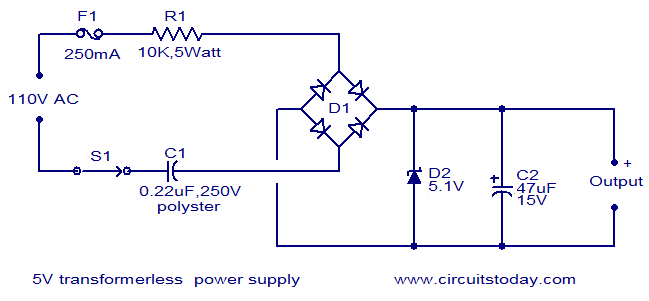
The circuit diagram illustrates a 5V transformerless power supply utilizing minimal components. The operation of this circuit is straightforward. Resistor R1 serves as a current limiter, while bridge D1 rectifies the mains voltage. The Zener diode regulates the output...

The transformer has two primary windings and six secondary windings; the two 120-VAC primary windings and the 6.3-VAC secondary windings are connected in parallel. Modules A and B are identical; therefore, only the components of Module A are specified....

This schematic represents a radio receiver circuit based on the TDA7088T, which is suitable for use in mono portable and pocket radios. The TDA7088T is a bipolar integrated circuit designed to operate with a minimal number of peripheral components...
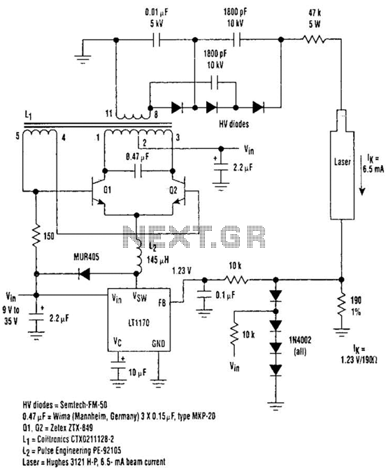
Driving Helium-Neon lasers can be greatly simplified using this power supply configuration. When power is applied, the laser does not conduct, and the voltage across the 190-ohm resistor is zero. However, a resonant circuit and a voltage tripler then...
This is a 300 W RF amplifier designed for FM transmission, capable of operating within the frequency range of 88 to 108 MHz. The amplifier utilizes two TP9383 transistors, enabling it to deliver up to 300 W of output...
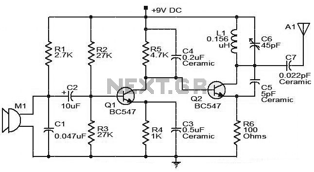
The moderate power FM transmitter circuit employs two transistors. The voice signals picked up by the microphone will be amplified by the transistor. The described FM transmitter circuit utilizes two transistors to facilitate the modulation and amplification of audio signals....