
microcontroller How does this power supply circuit work? (MCU + LM317)
")
The circuit described involves a PWM (Pulse Width Modulation) signal that is filtered by the combination of resistors R1, R2, and capacitor C1. This filtering process smooths out the PWM waveform to produce a more stable DC voltage. The operational amplifier, configured as a non-inverting amplifier, serves to amplify this integrated DC voltage. The gain of the op-amp is set by the resistors R6 and R7, which defines how much the input signal is amplified before being sent to the next stage of the circuit.
The LM317 voltage regulator plays a critical role in this configuration. It maintains a constant output voltage by providing a reference voltage of 1.25V between its output (OUT) and adjust (ADJ) pins. The output voltage is adjustable and depends on the ratio of resistors R2 and R5, as illustrated in the provided equation. The term I(adj) represents the adjustment pin current, which is typically very small but can influence the output voltage slightly. The relationship between the integrated DC voltage and the output voltage indicates that changes in the current through the adjustment pin directly affect the output voltage. This understanding is crucial for ensuring that the LM317 operates effectively within the circuit, particularly when interfacing with the microcontroller, which may require specific voltage levels for accurate operation.
In summary, the circuit's operation hinges on the interplay between the PWM filtering, the amplification by the op-amp, and the regulation provided by the LM317. Each component plays a vital role in ensuring that the desired output voltage is achieved and maintained, enabling reliable performance of the overall system.The filter R1, R2 and C1 integrate the PWM waveform. But what is the point of the op-amp It looks like a non-inverting amplifier to me, with the gain set by R6 and R7 - if I`m not mistaken. But why does the integrated DC voltage need amplification Perhaps, I don`t understand that part because I don`t understand how the Lm317 is working in conjunction with the MCU.
I understand that LM317 drops a reference 1. 25V between the OUT and ADJ pin (which should be across R5 in reference to the circuit) and the Vout is defined as 1. 25(1 + R2/R5) + I(adj. ) * R2. (from datasheet) Since the only variable is I(adj) in the above equation, am I correct in my understanding that the integrated DC voltage is actually changes the current and hence the output voltage
🔗 External reference
Related Circuits
The following circuit illustrates a 5 Zone Anti-Theft Circuit Diagram. This circuit is based on the CMOS 4050B IC. Features: the system may comprise in... The 5 Zone Anti-Theft Circuit utilizes the CMOS 4050B integrated circuit, which is a hex...
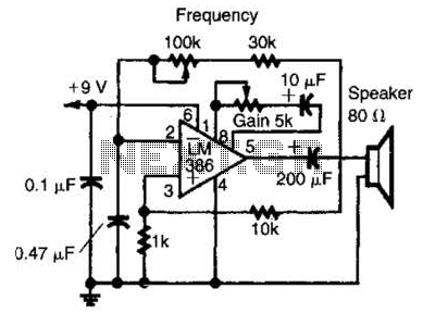
An LM386 audio power IC is configured as a feedback oscillator. It can operate with a supply voltage ranging from 6 to 12 V. The circuit is capable of driving a loudspeaker. The LM386 is a low-voltage audio power amplifier...
An audio power amplifier can enhance weak signals from devices like tuners, CD players, or tape decks to fill a room with sound. This article emphasizes the operating principles and circuitry of low-frequency power amplifiers utilizing bipolar junction transistors...
This circuit allows for the observation of movement between various stroboscopes. The generation of a rectangular signal is accomplished using an NE555 timer. It operates on a low power supply, which is created using a simple transformer (TR1), a...
A regenerative radio operates by feeding back a small portion of the amplified output from the detector into the input. This feedback mechanism enhances sensitivity significantly beyond what a detector can achieve on its own. The simple regenerative radio...
This article describes a band-pass filter circuit diagram utilizing transistors. A band-pass filter is an essential electronic circuit that allows signals within a certain frequency range to pass while attenuating frequencies outside that range. The circuit typically consists of a...