
Computer AC power source monitoring circuit

The circuit design incorporates a current transformer that senses the alternating current (AC) load typical in computer systems. This transformer is critical for monitoring the current flow in the power line, allowing for real-time status assessment. The LM393 comparator serves as a key component in this circuit, providing a means to compare voltage levels and generate an output based on the comparison results.
Upon powering the circuit, IC1 is responsible for setting the alarm time interval, which is crucial for the operation of the system. The circuit is designed to accept input signals labeled A, B, C, and D. The configuration of these inputs determines the operational state of the circuit. Specifically, when inputs B and D are high and A and C are low, the circuit is prepared to process the input time.
The circuit also features a frequency division mechanism that divides the input power frequency by two. This is particularly relevant when considering standard power frequencies of 50Hz or 60Hz, which are common in electrical systems worldwide. The timing calculations indicate that an output signal will be generated after approximately 87 minutes for a 50Hz input frequency and 73 minutes for a 60Hz input frequency.
The output from the decoder (DECODE() UT) becomes high at the end of the designated time interval, triggering the transistor VT1. This action activates the buzzer (HA), producing an audible alert. The duration of the buzzer sound is controlled by the resistor RI-I and capacitor CH, allowing for customization of the alarm duration based on user requirements or specific application needs. This comprehensive design facilitates effective monitoring and alerting in environments with significant power loads, enhancing operational safety and reliability. Circuit principle: computers AC power load is large, the use of the current transformer current sensing. It can be used to detect whether a current power line, determine its st atus. Schmitt is LM393 comparator circuit (A), after the power is turned on, set the alarm time interval by IC1 completed. When the input time (A, B, C, D) ended input binary code, 1C1 time interval can be set. B, D is set to the high level, A, and C is set to a low level. 1C1 input power frequency 1/2 division. If the power frequency is 50Hz, after about 87min, when power frequency is 60H, after about 73min, the output of the decoder (DECODE () UT) output high, VT1 conduction, HA buzzer sound, the sound of time from RI-I, CH decision.
Related Circuits
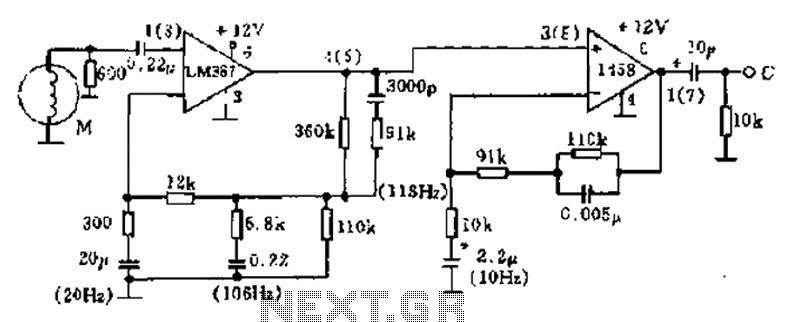
The phonograph pickup head is represented in the schematic as component M, which generates the pick-up signal and is processed through an LM387 amplifier circuit. The LM387 is part of the LM38X series, recognized for its advanced linear amplifier...

A simple battery charger designed for Nickel Metal Hydride batteries that require current-regulated charging. The charger delivers a charging current of 140 mA for efficient battery charging. The power supply section includes a 0-18 volt AC 1 Ampere step-down...
In this circuit, the 7815 regulates the positive supply, and the 7915 regulates the negative supply. The transformer should have a primary rating of 240/220 volts for Europe, or 120 volts for North America. The centre tapped secondary coil...
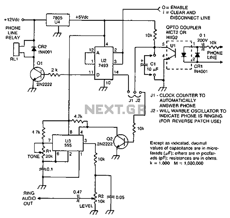
Check the loop circuit for an automatic telephone answering system or a tone generator for use in reverse automatic repair. The loop circuit in an automatic telephone answering system is designed to detect incoming calls and activate the answering mechanism....
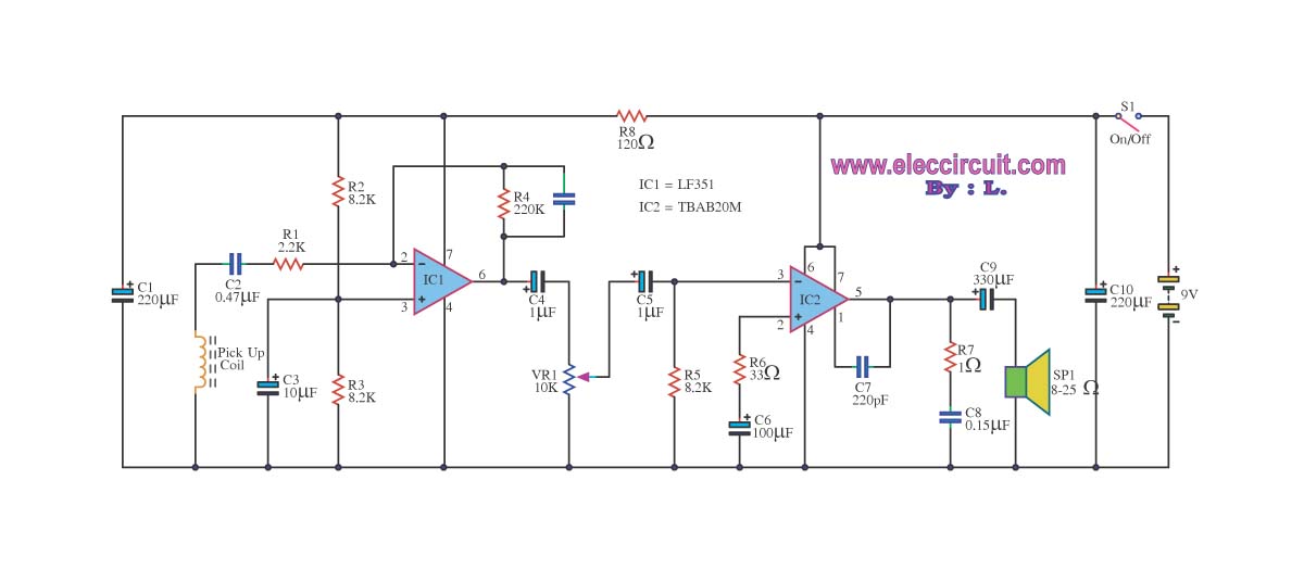
The circuit is designed to amplify telephone signals using a 2W+2W amplifier with an 8-ohm loudspeaker. It provides adequate sound output while maintaining good audio quality. The primary component of this telephone amplifier circuit is the IC LF351, which...
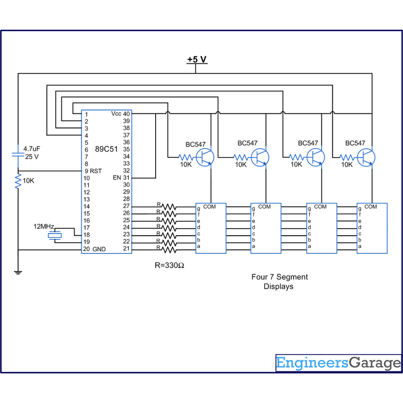
A digital clock displays time in a digital format. The circuit outlined here shows the time with double-digit minutes and two digits for seconds across four seven-segment displays. The segments of the displays are interconnected with the 8051 microcontroller...