
Quartz Controlled Bedroom Light Switch

The automatic light switch circuit operates using a photoresistor (LDR) and a transistor as the primary components. The circuit is designed to turn on the light automatically when ambient light levels fall below a certain threshold, making it ideal for nighttime use in bedrooms.
The LDR is connected in a voltage divider configuration with a fixed resistor. As the ambient light decreases, the resistance of the LDR increases, causing the voltage at the junction of the LDR and the resistor to rise. This change in voltage is used to control the base of a transistor, which acts as a switch.
When the voltage at the base of the transistor exceeds a certain level, the transistor enters saturation and allows current to flow from the collector to the emitter. This current can then be used to energize a relay or directly drive the light fixture, depending on the specifications of the components used.
The circuit should be powered by a suitable voltage source, ensuring that all components are rated for the voltage in use. Additionally, it is advisable to include a diode in parallel with the relay coil to prevent back EMF from damaging the transistor when the relay is de-energized.
This design offers a straightforward solution for automatic lighting control, enhancing convenience and energy efficiency in bedroom environments. Proper component selection and layout are crucial to ensure reliable operation and safety.Here is an ultra simple automatic light switch circuit for bedrooms. After construction,connect the input terminals of this circuit in parallel to the inte. 🔗 External reference
Related Circuits
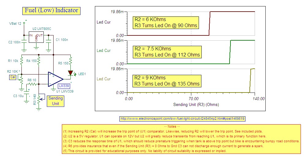
Research indicates that the sender will register a resistance of 100 ohms when the fuel tank is empty, making a trigger reading of 80 ohms optimal. The fuel gauge sender is a critical component in monitoring the fuel level within...
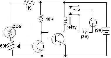
This circuit was submitted by Adam from Canada who is still at school. I have provided the text. The two transistors are used as a direct coupled switch, Adam used 2SC711 but any general purpose transistor will do e.g....

The circuit below uses a CMOS dual D flip flop (CD4013) to toggle a relay or other load with a momentary push button. Several push buttons can be wired in parallel to control the relay from multiple locations. A...
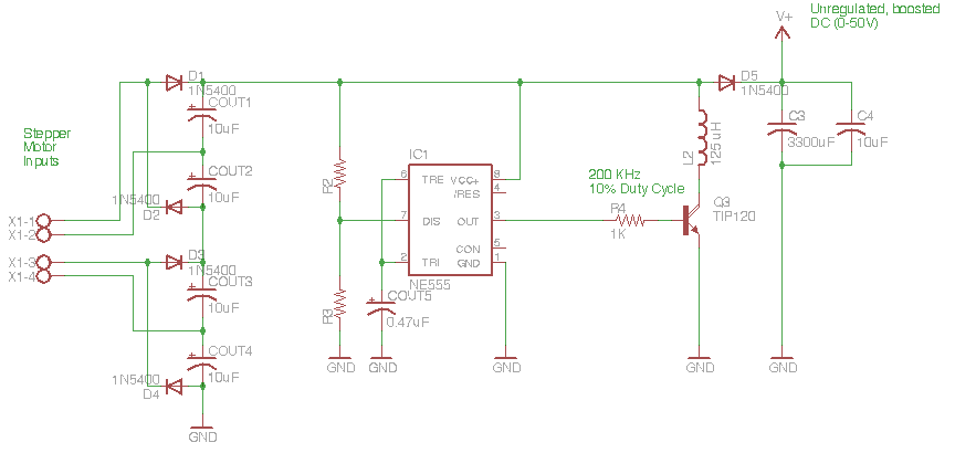
The circuit depicted in the schematic below represents an enhanced generator electronics system. It is an unregulated switcher designed to maximize sound output while ensuring prolonged CPU operation. This circuit efficiently transfers electrical energy from the generator, outperforming traditional...

The voltage-controlled gain amplifier utilizes a FET gate voltage and the drain-source resistance (RSD) to approximate a logarithmic relationship. The integrated circuit chip LM307 is employed in the amplifier circuit with the inverting input configuration. In the circuit, RSD...
4QD manufactures motor speed controllers, and all their H bridges utilize PWM. This is a simple switch circuit designed for reversing and stopping a motor without speed control. Two inputs, A and B, control the bridge. When both inputs...