
Condenser Mike Pre-Amplifier Circuit

The circuit design described incorporates a condenser microphone, which is known for its high sensitivity and ability to capture a wide range of sound frequencies. The inclusion of an FET amplifier within the microphone housing is critical for boosting the weak electrical signal generated by the microphone. This FET amplifier ensures that the output signal is strong enough to be processed by the subsequent amplification stages.
The first amplification stage utilizes a BC149C transistor, which is configured for current series feedback. This configuration allows for better linearity and stability in the amplification process, ensuring that the sound signals are reproduced accurately without significant distortion. The choice of the BC149C transistor is appropriate due to its low noise characteristics and suitability for audio applications.
The second amplification stage employs a BC147B transistor in a voltage shunt feedback configuration. This arrangement is effective for providing additional gain while maintaining a stable output. The feedback mechanism helps to control the gain and enhances the linearity of the amplifier, making it suitable for detecting subtle sound variations, such as whispers.
The circuit operates on a supply voltage of 4.2 volts, which is relatively low, making it suitable for battery-powered applications. The use of a 1kΩ resistor (R9) helps to regulate the current flow, but this component can be adjusted to accommodate different supply voltages. This flexibility in power supply allows the circuit to be adapted for various applications.
To further enhance the sensitivity and gain of the circuit, the resistance value of R6 can be modified. By reducing R6 to 47Ω or 22Ω, the gain can be increased, making the circuit more responsive to quieter sounds. Additionally, using a lower supply voltage of 3V and eliminating R9 altogether can also lead to a significant increase in gain, which may be advantageous in specific scenarios where maximum sensitivity is required.
Finally, the recommendation to house the microphone in a small round enclosure not only protects the sensitive components but also aids in sound collection by minimizing external noise interference. This design consideration is essential for applications where clarity and precision in sound detection are paramount. Overall, this circuit design offers a versatile solution for various sound detection applications, combining sensitivity, flexibility, and ease of use.need often arises for a sensitive sound pick-up device, whether it is to be used as a simple microphone or a more exotic device as a sound operated alarm, a bugging device or a sound operated flash (for stop action photography) the list is quite unending. The circuit given employs a condenser microphone as the transducer. Since output of the conde nser microphone is quite low, it usually has an FET amplifier built into the case. The output of condenser microphone is fed to a two stage amplifier. Transistor T1 (BC149C) utilising current series feedback forms the first stage. The second stage comprising transistor T2 (BC147B) is connected in the voltage shunt feedback configuration. These two stage provide sufficient gain to pick up even the slightest whisper. The circuit requires a 4. 2 volt supply. This may be obtained, as in the prototype, with a 1k © (R9) resistor as shown in the diagram. The value of this resistor may be altered. to suit a supply voltage other than 6 volts. Circuit`s gain can be increased by reducing the value of R6 to 47 © or 22 ©, depending on the input sensitivity of the main amplifier system.
Increase in gain was also observed by using 3V supply and eliminating R9 altogether. The microphone should be housed in a small round enclosure. 🔗 External reference
Related Circuits
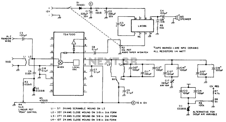
This direct-conversion receiver utilizes a TDA7000 integrated circuit (IC) and incorporates an LM386 audio amplifier. The TDA7000 serves as the mixer and local oscillator (L.O.) section. The frequency control can be achieved using either an air variable capacitor or...

Three power levels are provided by the two logic inputs of this enhanced circuit. R5, D4, D5, and O2 create a power supply for the logic integrated circuit. These components can be excluded if an alternative low voltage source...
In all the houses exist the bells in the door. All want, they have the possibility of being possible to change the intensity, the tone of sound. With this circuit we have this possibility. With the materials round the...
This is a simple circuit designed for an audio amplifier project to control the speaker output relay. The purpose of this circuit is to manage the relay that activates the speaker output in the audio amplifier. The circuit is...

This sensor switch circuit features nine channels and consists of three integrated circuits along with several resistors. The 74HC147, which has a high input impedance, enables the use of 4.7 MΩ resistors to establish a logic level "high" for...
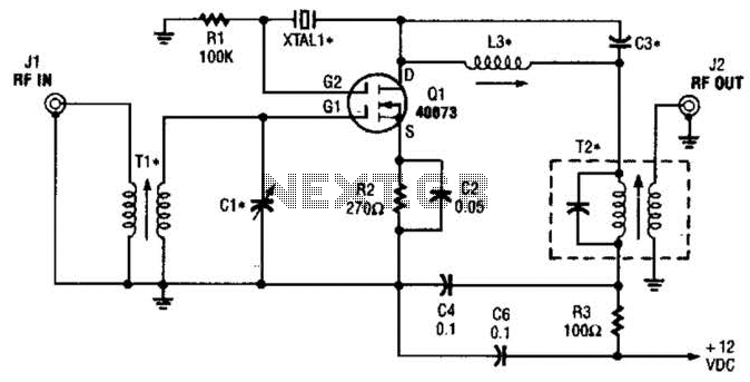
The second gate (G2) of a MOSFET can be utilized to integrate a crystal oscillator within the same stage as a frequency mixer. While this technique is common in tube technology, it is rarely implemented in dual-gate MOSFET circuits....