
Conducting pipe control rechargeable short delay circuit 2

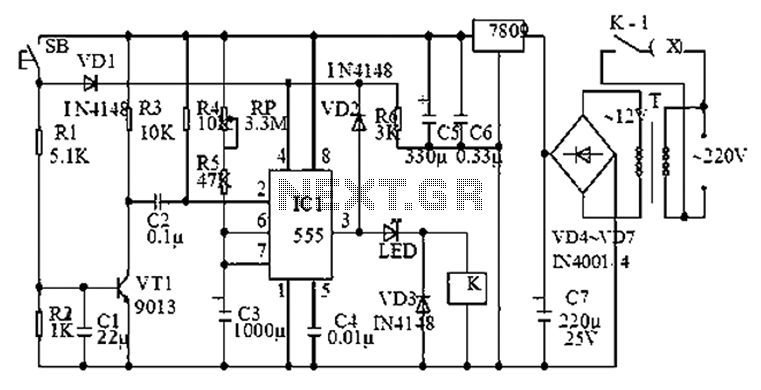
The rechargeable short delay circuit is designed for applications where a controlled delay is necessary before activating a connected load, such as a valve or actuator in a conducting pipe system. The core components of the circuit include a power supply, a timing mechanism, and two adjustment potentiometers (RP), which are crucial for customizing the delay duration.
The power supply can be a rechargeable battery or a DC power source, providing the necessary voltage and current for the circuit's operation. The timing mechanism typically consists of a resistor-capacitor (RC) network that determines the delay period. The two potentiometers allow for fine-tuning of both the resistance and capacitance values, enabling the user to adjust the timing characteristics according to specific application requirements.
When the circuit is activated, it begins charging the capacitor through the resistor. The time it takes for the capacitor to reach a certain voltage level, determined by the potentiometer settings, dictates when the output will trigger. This output can be connected to a relay, transistor, or any other switching device to control the load in the conducting pipe system.
The flexibility offered by the dual potentiometers enhances the circuit's versatility, making it suitable for a variety of applications requiring precise timing control. Proper implementation of this circuit can lead to improved efficiency and reliability in systems that rely on timed operations.Conducting pipe control rechargeable short delay circuit 2 Adjustment potentiometer RP, allows the delay time of several hundred milliseconds to several seconds.
Related Circuits
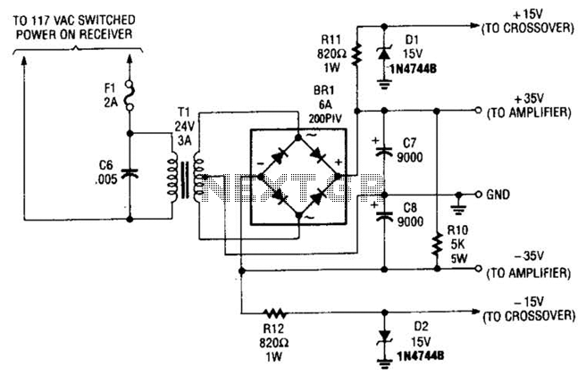
This power supply is designed to power a 100-W low-frequency amplifier and is capable of supporting various mono or stereo amplifiers within the medium power range, specifically those that require 30 to 35 V. The power supply circuit is engineered...
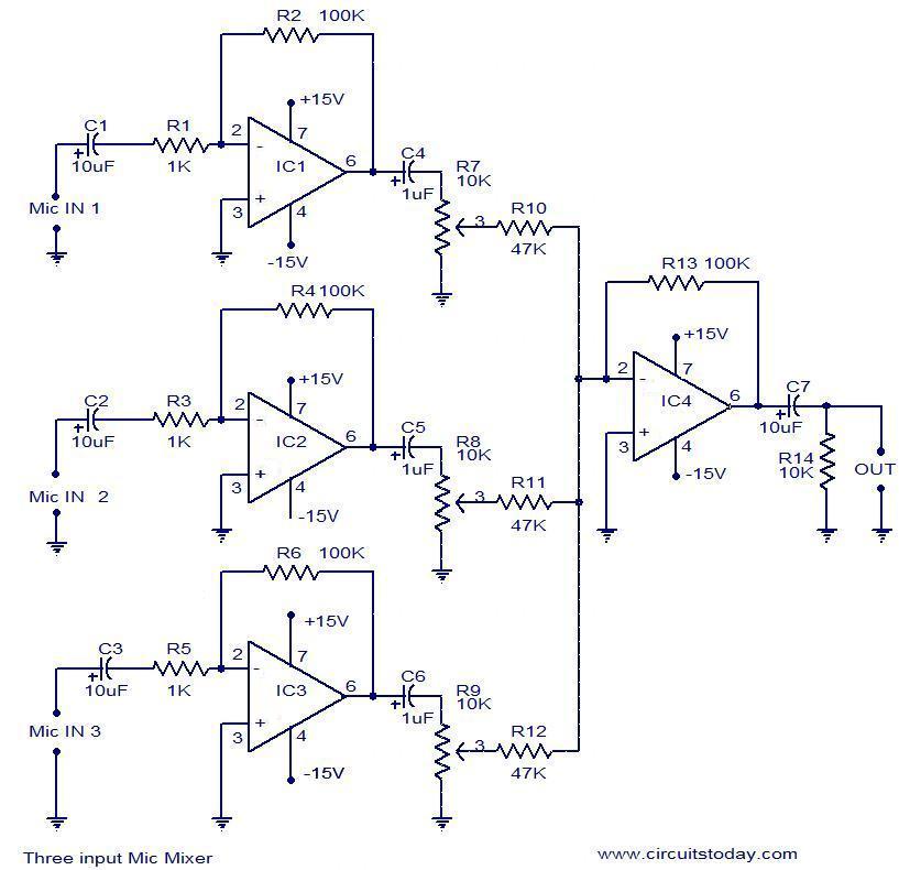
This document outlines a simple three-input microphone mixer circuit utilizing the widely used uA741 integrated circuits (ICs). Four uA741 ICs are employed in this design. IC1, IC2, and IC3 function as preamplifiers, each providing a gain of approximately 40...
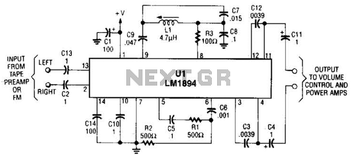
UL is a dedicated integrated circuit (IC) from National Semiconductor that achieves up to 10 dB noise reduction through an adaptive bandwidth scheme and a psychoacoustic masking technique. The UL integrated circuit is designed to enhance audio performance by significantly...

The phase and neutral wires from the power source have already been connected to electrical appliances such as fans and light points. According to the UPS connection diagram, an additional phase wire should be connected to those appliances where...

This circuit diagram represents a logic probe based on a single CMOS integrated circuit (IC). The logic probe indicates three conditions: High, Low, and Pulsing. Additionally, no LEDs will illuminate when the probe input is in a high-impedance state,...
The 555 timer is commonly used in time-based circuit designs, particularly in monostable configurations. This setup is straightforward and requires only a few resistors and capacitors to achieve triggering. However, external interference can affect the operation of the circuit...