
Flood Sensor with 12F683

The water detection circuit is designed to monitor the presence of water through the use of conductive probes. The microcontroller's low-power state is a critical feature that extends battery life, entering this state for a fixed duration of 10 seconds between readings. During this period, if water is detected, the system will not respond until the microcontroller exits the low-power mode, which may delay the alarm activation. Therefore, the placement of probes is crucial; they should be positioned closely together without contact to maximize the detection area while minimizing the risk of false readings due to short circuits.
The circuit includes two LEDs: a red LED for alarm indication and a green LED for battery status. Upon powering up, the system performs a self-test where both LEDs and the piezo buzzer are activated to confirm functionality. The microcontroller continuously checks the probes for water presence and monitors the battery voltage. A voltage threshold of 7V has been established; when the voltage falls below this threshold, the red LED will flash, and the piezo will emit a short beep as a warning to replace the battery.
In alarm mode, triggered by water detection, the red LED lights up continuously while the piezo buzzer emits a loud alarm sound. This state persists until the user presses a reset switch (S1), allowing the system to return to normal operation. Regular maintenance of the probes is advised, especially since they are made of aluminum, which is preferred over copper due to its resistance to corrosion. The effectiveness of the water detection system is enhanced by ensuring the probes remain clean and functional, as any buildup or deterioration could affect performance.
The external placement of the LEDs and piezo buzzer is a practical solution to space constraints within the enclosure, ensuring that visual and auditory alerts are easily perceivable. This design consideration enhances user interaction with the device, making it clear when the system is in an alarm state or requires maintenance. Overall, the water detection circuit is a reliable solution for monitoring water presence, with built-in features for battery management and user notifications.The water detection time is less than 10 seconds. Since the microcontroller enters a low consumption state between readings to preserve battery life, this state is always 10 seconds long. If water reaches the probes while being in the low power state it will have to wait until it finishes the sleep state before it can trigger the alarm.
Also, the probes should be placed not to far apart from each other and they never should touch each other. The more probe area available for water sensing the better. After everything is checked ok the detector will enter it's normal state. Every 10 seconds it will check the probes and the battery's voltage. The box that I used did not had enough room for all components, so I had to place both leds and piezo on the exterior of the box. That detail didn't make any difference since the leds should stay visible and the piezo free to make the loudest sound possible.
The probes can be made from any conductive material, but I preferred not to use copper because it deteriorates with time. In my opinion a good material to be used is stainless steel or aluminium. However, maintenance should be done from time to time checking the probes and testing them with water.
Turning on the circuit, both leds and piezo are tested. Also the probes are checked. If the probes are sensing water or any kind of leakage it will turn on the red led and it will trigger the piezo. If water gets between the probes the detector will enter the alarm mode where the red led will turn on and the piezo will start making a loud sound.
The detector will keep itself in alarm mode until S1 is pressed. If the battery's voltage is good, the green led will flash every 10 seconds but if the voltage reaches 7V the red led will flash every 10 seconds and the piezo will make a short sound to indicate it's time to change the battery. The probes I used in my project are made from aluminium. 🔗 External reference
Related Circuits
This circuit consists of an infrared phototransistor and an infrared LED. The transducer operates on the principle of light reflection, specifically infrared light. The skin serves as a reflective surface for the infrared light, and the density of blood...

This is a rather sensitive circuit which will detect minute variations of a magnetic field, particularly the Earth magnetic field. The principle is based on an audio beat tone generated by two identical oscillators. These must be built in...
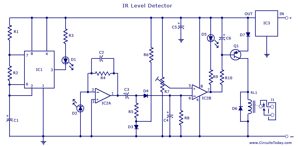
An infrared (IR) sensor or detector circuit diagram utilizing a 555 integrated circuit (IC), primarily employed as a water level or liquid level sensor and proximity detector circuit. The described circuit employs a 555 timer IC configured in a monostable...

The AD537 utilizes two reference outputs—one fixed at 1 V and the other varying with temperature at a rate of 1 mV per °K. At 0°C, the 1-V reference multiplied by 0.273 balances this voltage to produce a zero...
It's basically a photovore with a couple tactile sensors. It's rather complex but can give neat behaviors with modifications to the circuit. At this point I don't have any plans to give more information on this circuit so your...
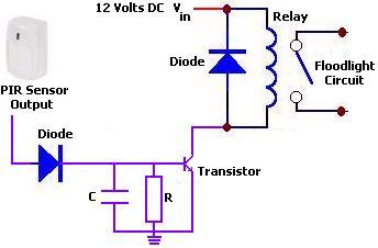
The circuit illustrates a 12V PIR sensor timer circuit diagram. Features include a 12 Volt DC supply, capable of activating a floodlight or other devices for a specified duration. The 12V PIR sensor timer circuit is designed to detect motion...