
Sound Effects Generator Circuit

As more outputs from the counter activate, the base current to Q1 increases, thereby raising the VCO's oscillation frequency. The VCO is constructed using IC2-a, IC2-b, and Q1, with the timing network comprising diodes D1 through D4, capacitor C1, resistor R10, and resistor R11. The diode bridge operates primarily as a voltage-controlled resistor. The audio output buffer amplifier utilizes the remaining four gates from IC2, configured in parallel. While the output volume is adequate for experimental applications, the addition of an external amplifier or speaker may be considered for enhanced audio performance.
The circuit operates on a feedback loop that allows the binary counter's output to dictate the frequency of the VCO, establishing a dynamic interaction between the components. The use of the potentiometer R11 provides an adjustable parameter for initial frequency settings, enabling fine-tuning of the oscillation characteristics. The D/A converter's resistive network translates the digital outputs from the counter into a corresponding analog control voltage, which modulates the VCO's frequency.
The VCO itself, through its configuration with IC2 and transistor Q1, serves as the primary oscillator, with the timing network determining the rate of oscillation. The inclusion of the diode bridge as a voltage-controlled resistor is critical for achieving variable resistance based on the control voltage, thus influencing the frequency output. The buffer amplifier ensures that the output signal is robust enough for driving subsequent stages, while also maintaining signal integrity.
In practical applications, the circuit can be employed in sound synthesis, frequency modulation, or other audio signal processing tasks. For users seeking enhanced audio output, integrating additional amplification stages or high-fidelity speakers would improve the overall performance and sound quality of the circuit. The circuit consists of four parts: a binary counter, a D/A converter, a VCO, and an audio output amplifier. The speed at which the counter counts depends on the frequency of the output of the VCO, which in turn is determined by the output of the counter.
That feedback loop gives this circuit its characteristic output. The initial frequency of oscillation is determined by potentiometer Rll. The VCO first oscillates at a relatively low frequency, and it gradually picks up speed as the control voltage supplied by the D/A converter increases. The D/A converter is simply the group of resistors Rl tlirough R8. When none of ICl`s outputs is active, little current will flow into the base of Ql, so the VCO`s control voltage will be low.
As more and more counter outputs become active, base current increases, and so does the VCO`s frequency of oscillation. The VCO itself is composed of lC2-a, lC2-b, and Ql; the timing network is D1 through D4, 01, RIO, and Rll.
The diode bridge functions basically as a voltage-controlled resistor. The buffer amplifier is made up of the four remaining gates from IC2, all wired in parallel. The volume is sufficient for experimental purposes, but you might want to add an amplifier, speaker, or both.
Related Circuits
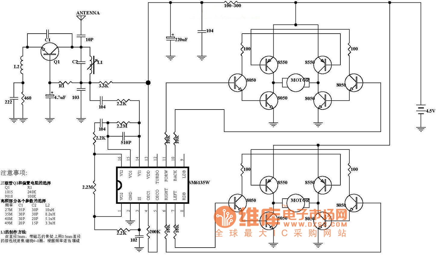
The diagram illustrates the principle circuit of a radio control car receiver. Important notes include the selection of transistor Q1, which is specified as either 1815 or 9018, along with the bias resistor R1, which has values of 240K...
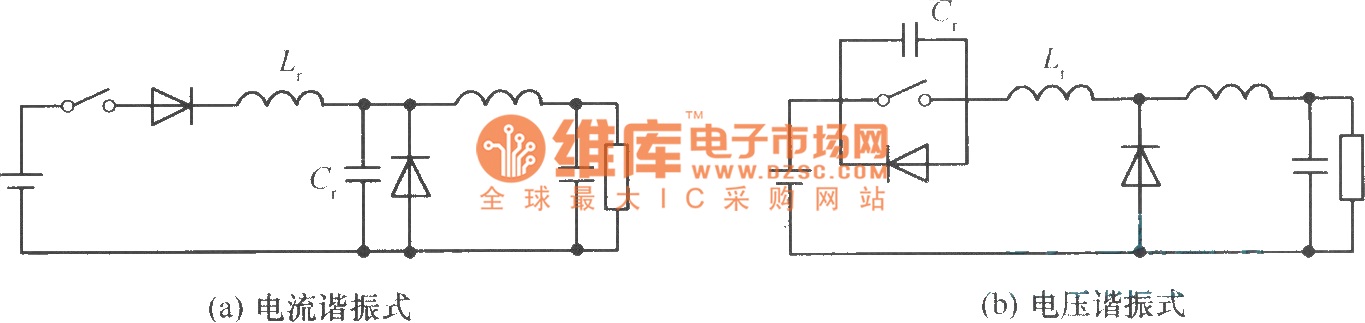
In a commonly used switching stabilized voltage supply, a resonant switch can be utilized to replace the shape of a step-down converter, resulting in a resonant converter circuit. The diagram illustrates the transformation from a step-down converter to a...
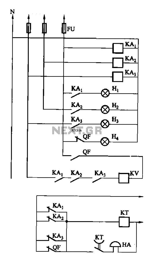
The circuit features intermediate relays KAi, KA2, and KA3, which are connected to the outlet end of the low-voltage circuit breakers. An alarm circuit is linked to a backup power supply or a battery power supply. This configuration serves...
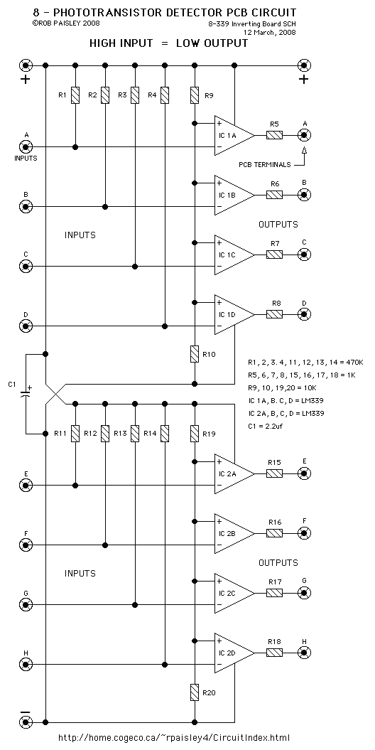
The circuit on this page is for a simple light detector circuit board that has 8 detectors that can be used with visible or infrared light systems. The detectors use LM339 voltage comparators as the active element. Phototransistors or...
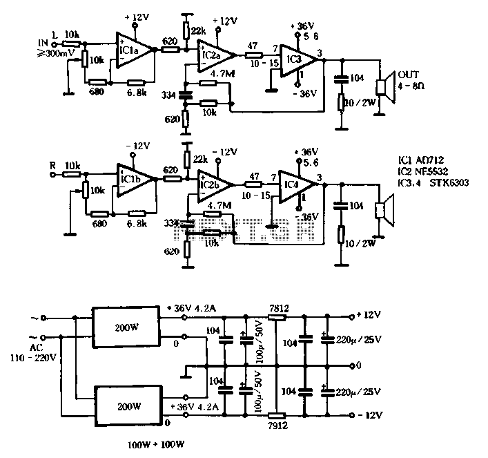
The T amplifier circuit schematic section is illustrated in Figure 3-51. It utilizes the Japan Sanyo STK6303 Pina, which is a high-power thick film integrated circuit. The maximum power supply voltage is 36V, and the output current can reach...
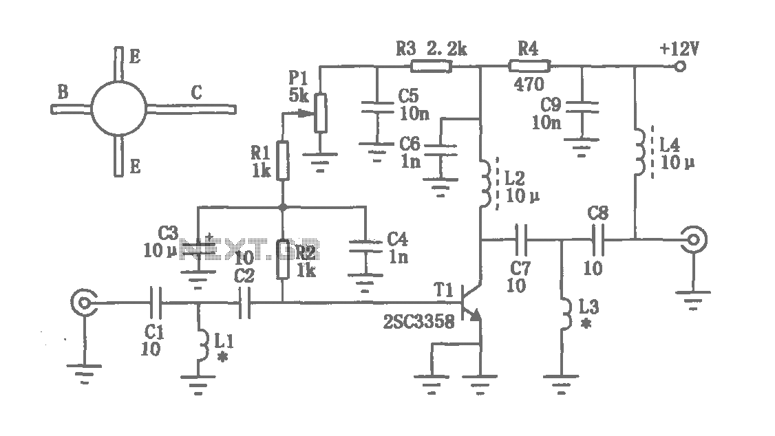
The circuit depicted in the figure operates within a frequency range of 400 to 850 MHz, designed as a UHF amplifying circuit. For optimal performance and results, it is recommended that the circuit be manufactured using silver-tin processing techniques. The...