
Short Tester For 120V Equipment Circuit

The circuit functions as a protective measure for vintage or malfunctioning electronic devices. It is particularly useful for equipment that has not been tested or assessed for faults, as it helps to mitigate the risk of causing additional damage during troubleshooting or repair efforts.
At its core, the circuit may incorporate a current-limiting resistor, a fuse, or a resettable polyfuse to safeguard the device from excessive current flow. The use of a diode can also be beneficial, as it allows current to flow in one direction while blocking reverse polarity, which can be a common issue with older devices.
In practical applications, the circuit can be connected in series with the power supply of the equipment. When powered on, the circuit will monitor the current flowing to the device. If the current exceeds a predetermined threshold—indicating a potential short circuit or fault—the protective elements will activate, either cutting off power or limiting the current to prevent further damage.
This approach not only protects the device but also allows for safe diagnostics and repairs. Users can confidently test and work on old equipment without the fear of exacerbating existing issues. Do you deal with old equipment in unknown condition If so, this little circuit could keep you from causing further harm to already shorted devices.
Related Circuits

One of the major problems that must be addressed in electronic circuit design is the generation of low voltage DC power supply from mains power to energize the circuit. In electronic circuit design, the conversion of mains AC voltage to...

The circuit depicted is a 12 kHz intermediate frequency oscillator designed for an alarm system. It employs a variable feedback oscillation circuit where the oscillation frequency is primarily determined by a quartz crystal. Capacitors C1 and C2 are used...
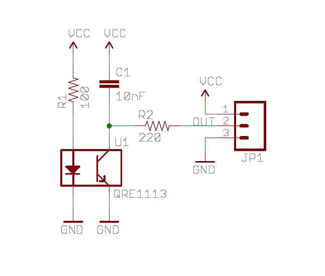
A real-time clock turns off the counter at night to conserve power. When a bee crosses under the LED, the light is reflected back to the sensor, which is a phototransistor, and triggers a digital input to the Arduino...
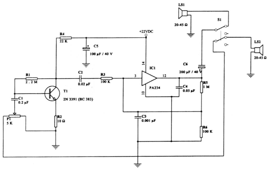
This intercom circuit is versatile and can be utilized in various applications. It operates at 22V, although it may function at a lower voltage (experimental testing is suggested). The circuit utilizes a loudspeaker with an impedance of 20-45 Ohms...

This circuit is designed as a warning flasher to alert road users to dangerous situations in low-light conditions. It can also function as a bicycle light, subject to applicable traffic regulations. White LEDs are recommended for use as a...
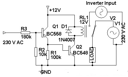
Three weeks ago, an inverter circuit diagram was introduced; however, the circuit did not include the AC to inverter switching part. Today, a 230 Volt AC to inverter switching circuit diagram is being presented. The circuit demonstrates inverter switching....