
low voltage high current time delay circuit

The circuit begins with the LM339 quad voltage comparator, which is designed to compare input voltages and produce a corresponding output signal. In this setup, three of the four comparators are employed to enhance the output current capability. By connecting them in parallel, the effective output current is increased, allowing for the control of a medium power PNP transistor.
The PNP transistor (2N2905) serves as an intermediary switch that regulates the current flowing to the high current NPN transistor (TIP35). When the output from the LM339 indicates that the input conditions are met, the PNP transistor is activated, allowing current to flow to the TIP35. The TIP35 is capable of handling high current loads, making it suitable for applications requiring up to 5 amps.
The power supply for this circuit is provided by two fresh alkaline D batteries, which deliver a low voltage suitable for the operation of the comparators and transistors. The LM339 operates effectively within a range of supply voltages, making it compatible with the battery voltage.
In summary, this circuit effectively combines the functionality of a voltage comparator with the switching capabilities of transistors to create a time delay mechanism while controlling a high current output. The parallel configuration of the comparators ensures sufficient drive capability for the PNP transistor, which in turn activates the TIP35 to manage the high current load. This design is particularly useful in applications requiring precise control of high current at low voltage levels.In this circuit a LM339 quad voltage comparator is used to generate a time delay and control a high current output at low voltage. Approximatey 5 amps of current can be obtained using a couple fresh alkaline D batteries. Three of the comparators are wired in parallel to drive a medium power PNP transistor (2N2905 or similar) which in turn drives a high current NPN transistor (TIP35 or similar)..
🔗 External reference
Related Circuits
This circuit is designed to detect incoming calls on a cellular phone, even when the phone's ringer is turned off, by utilizing a flashing LED. The device should be positioned a few centimeters away from the cellular phone, allowing...
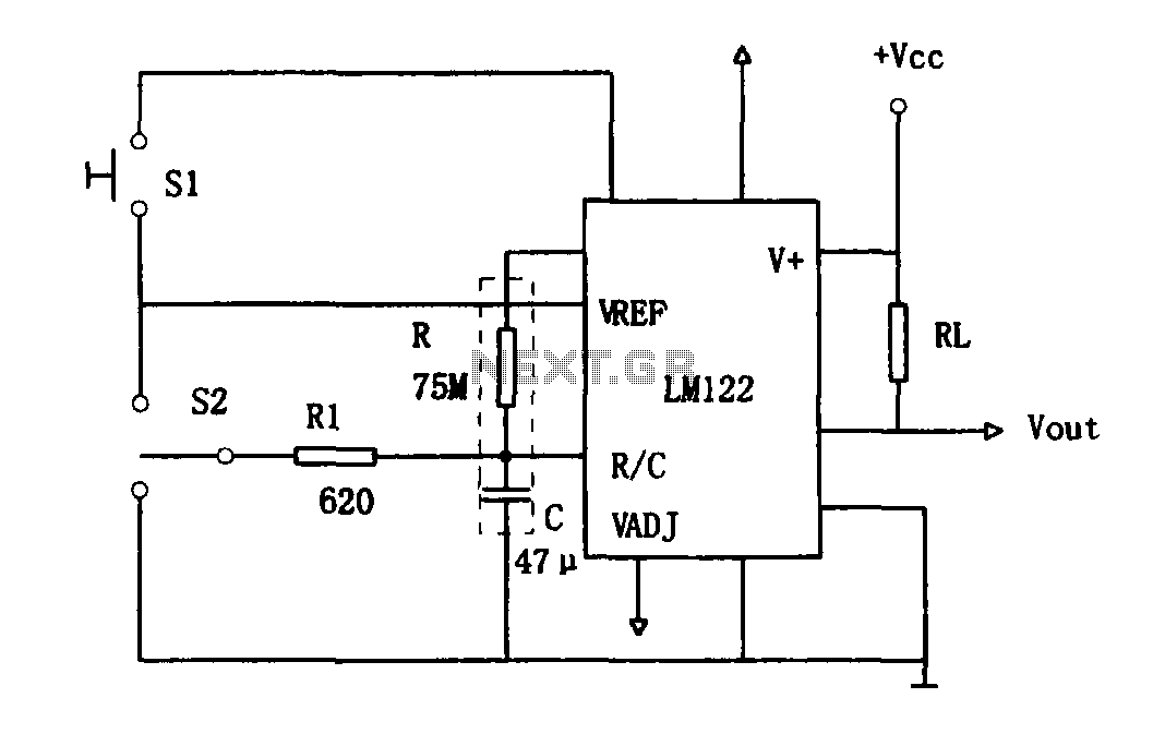
As illustrated in Figure 1, the circuit utilizes an LM122 timer. The circuit's start, reset, and stop functions are managed through switching operations. Switch S1 initiates the timing sequence when the timer is activated; thereafter, this switch has no...
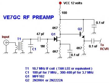
This is a simple VE7GC Popcorn RF preamplifier designed by Dick Pattinson. The circuit features a single tuned circuit at the input stage, allowing direct connection to a mixer or product detector in a straightforward receiver project. Adjustable RF...
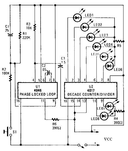
An electronic circuit for a roulette wheel can be constructed using a 4046 Phase-Locked Loop (PLL) that includes a Voltage Controlled Oscillator (VCO), two phase comparators, a source follower, and a Zener diode to generate a low-frequency pulsed output...
This three-band equalizer circuit is an active filter network designed for bass, midrange, and high audio frequencies. It utilizes the LM833 operational amplifier from National Semiconductors. The output of this three-way graphic equalizer is intended to be DC coupled;...
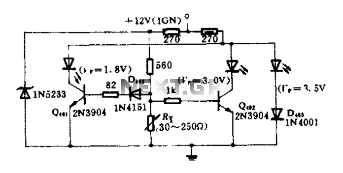
The circuit diagram illustrates how an oil pressure sensor is transformed into a variable resistor, denoted as Rt. Variations in Rt lead to changes in the biasing of each transistor, which in turn controls three LEDs (red, yellow, and...