
Commercial Stun Gun Circuit

Now, Q1 draws a significant collector current through the primary coil, creating a substantial magnetic field within the magnetic core of transformer T1. As the magnetic field intensifies due to the increasing collector current, both the feedback and secondary coils generate an opposing magnetic flux, which results in a negative electromotive force (EMF). This negative EMF is blocked by 1N4007 diodes in the secondary circuit. However, the negative EMF from the feedback coil is directly applied to C1, causing diodes D1 and transistor Q1 to enter the cutoff region.
Consequently, the collector current is interrupted, leading to a rapid collapse of the magnetic field within the core. At this point, the feedback and secondary coils produce an EMF that counteracts the reduction in flux. A positive EMF is applied to C1 from the feedback coil, and an additional positive EMF is applied to the 220 nF capacitor (C2). The secondary circuit is now complete, and C2 begins to charge through the 1N4007 diodes and the primary winding of transformer T2.
Once the voltage across C2 surpasses 3000V, the spark gap activates, discharging all the energy stored in C2 into the primary winding of T2. This results in the generation of approximately 100 kV pulsed high voltage output at the secondary of T2. A 1MΩ resistor serves as a bleed resistor. Meanwhile, due to the positive EMF from the feedback coil, C1 begins to charge again, and diodes D1 and Q1 resume conduction. Diode D2 and resistor R2 provide a return path for the current flowing through the feedback coil during this cycle, allowing the entire process to repeat.
The described stun gun circuit operates through a self-oscillating mechanism, where the interaction between the feedback coil and the charging capacitors enables it to produce high-voltage pulses efficiently. The use of careful timing and component selection ensures the rapid cycling necessary for generating the desired output voltage while maintaining circuit stability. Proper thermal management and component ratings are essential to ensure reliability and safety when operating at such high voltages.A commercial stun gun circuit which produces about 100KV pulses from a 9V battery is shown in Figures 1-2. The heart of the circuit is a power oscillator built around Q1. When the switch S1 is closed, C1 is charged through 1K resistor and the feedback coil. Q1 turns ON and saturates rapidly when the voltage across C1 is about 1.3V (Vf_diode+VBE).
Now, Q1 pulls a large collector current through the primary coil and a large magnetic field is developed within the magnetic core of T1.
As the magnetic field increases due to increasing collector current, both feedback and secondary coils develop an opposing flux which results in negative EMF. This negative EMF is blocked by 1N4007 diodes in the secondary circuit. However, the negative EMF of the feedback coil is directly applied at C1 and forces D1 and Q1 to go into cut-off region.
As a result, collector current is cut and the magnetic field within the core collapses rapidly. Now, feedback and secondary coils develop an EMF which counteracts the decrease in flux. So a + EMF is applied at C1 by the feedback coil, and a + EMF is applied at 220nF capacitor (C2). Secondary path is now completed and C2 begins to charge through 1N4007 diodes and the primary of T2.
As the voltage across C2 exceeds 3000V, spark gap fires and all the energy of C2 is damped on the primary of T2.
The result is about 100KV pulsed HV output at the secondary of T2. 1M resistor is the bleeding resistor. Meanwhile, due to + EMF of the feedback coil, C1 charges again, and D1 and Q1 start conducting. D2 and R2 provide a current return path for the feedback coil during this cycle. And the whole cycle repeats... By 4beowulf7 - [email protected]
Related Circuits
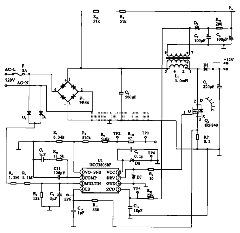
A typical laptop power adapter circuit converts an AC input of 22V through a rectifier and filter circuit to produce an output of +30V DC. This voltage is then processed by a switch oscillation circuit (U1, UCC38050P), which controls...
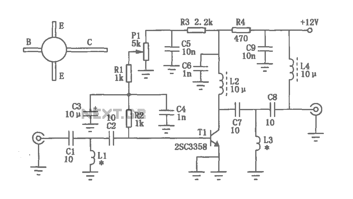
The amplification of this circuit is approximately 12,000 times, with a bandwidth ranging from 0.5 to 14 MHz. The input resistance is 700 ohms, while the output resistance is 35 ohms (measured at 5 MHz). The output noise level...
The circuit depicted in the figure operates within a frequency range of 400 to 850 MHz, designed as a UHF amplifying circuit. For optimal performance and results, it is recommended that the circuit be manufactured using silver-tin processing techniques. The...
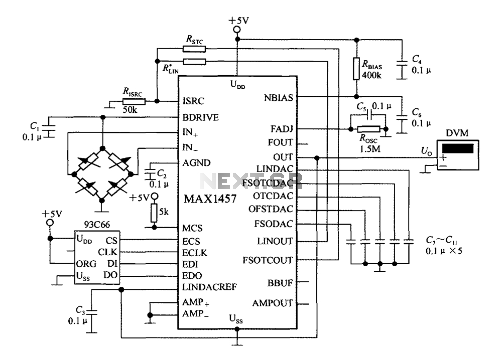
The circuit diagram illustrates a digital precision pressure tester using the MAX1457 integrated circuit with an external ROM selection of the 93C66 type, which is a 4096-bit E2PROM. Upon powering on, the MCS pin is pulled to a high...
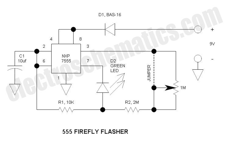
This circuit operates similarly to a standard 555 astable timer, with the distinction that the LED is integrated into the capacitor reset path. Consequently, when pin 7 discharges capacitor C1 to ground, a relatively high current flows through the...
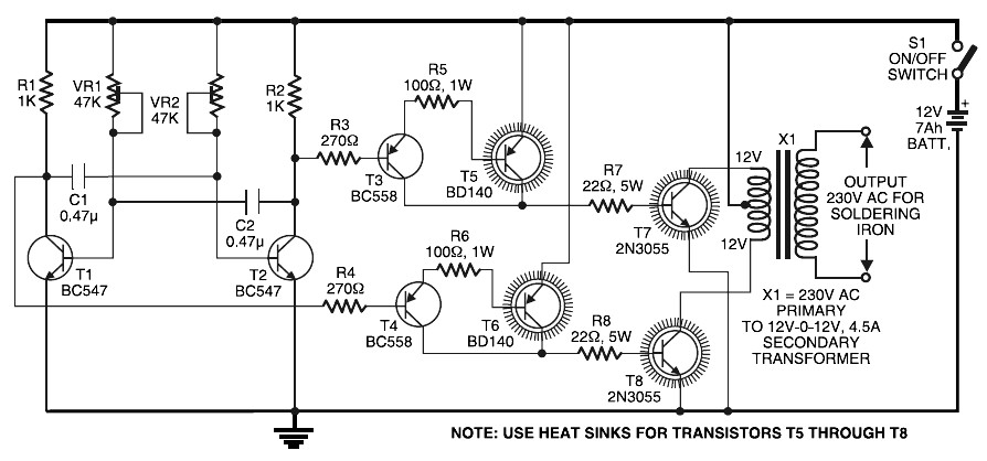
Simple Inverter for Soldering Iron. This is a straightforward and cost-effective inverter designed to operate small power soldering irons (25W, 35W, etc.) in the absence of mains supply. The circuit requires eight transistors along with several resistors and capacitors....