
Contrast meter

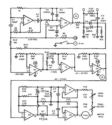
The described circuit employs a photocell (R1) as a light sensor, effectively functioning as a variable resistor whose resistance decreases with increasing light intensity. The configuration of R1 and R2 forms a voltage divider that sets a reference voltage at the non-inverting input of the operational amplifier (IC1). The operational amplifier, a 741 type, is a general-purpose device capable of amplifying the difference between its two inputs. The inverting input is grounded through resistor R3, which establishes a stable reference point.
When switch S1 is pressed, it modifies the circuit by introducing another voltage divider, which adjusts the voltage at the inverting input. This additional divider can be utilized to set a threshold level for the light detection, allowing the op-amp to respond to specific light conditions. The output of the op-amp is influenced by the voltage levels at both inputs; as the light intensity increases, the voltage at the non-inverting input rises, leading to a higher output voltage from the op-amp.
The connection of the photocell in a bottle cap with a small aperture ensures that only a limited amount of light can reach the sensor, enhancing sensitivity and accuracy in measuring light intensity. The use of potentiometer R5 allows for fine-tuning of the circuit, accommodating variations in the power supply voltage or the specific characteristics of the photocell being used. This calibration is crucial for applications where precise light measurements are required. Overall, this circuit design provides a functional approach to light sensing and measurement, with potential applications in automatic lighting systems, light-level monitoring, and other photometric applications.One leg of the photocell (Rl) is tied to the +15 volt supply and the other end is connected to ground through resistor R2, forming a voltage-divider network. The non-inverting input of the 741 op amp, IC1, is tied to the junction formed by Rl and R2, while its inverting input is grounded through resistor R3.
When switch SI is pressed, another divider network is formed, reducing the voltage applied to the inverting input of the op amp. When light hits the photocell its resistance begins to decrease causing a greater voltage drop across R2 and a higher voltage to be presented to the non-inverting input of IC1.
This causes IC1 to output a voltage proportional to the two inputs. The circuit gives a meter reading that depends on the intensity of light hitting photocell Rl; therefore, Rl should be mounted in a bottle cap so that the light must pass through a 3/16 inch hole. Potentiometer R5 is used to adjust the circuit for the negative you're working with.
Related Circuits
The ESR Meter functions as an AC Ohmmeter equipped with specialized scales and protective circuitry. It continuously measures the series resistance in electrolytic capacitors, operating at a frequency of 100 kHz to minimize the capacitive reactance factor. The series...
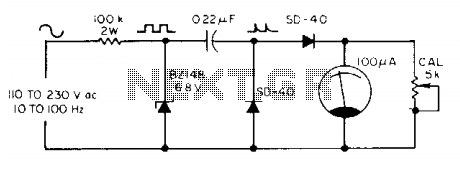
The meter utilizes a zener diode to convert input sine waves into square waves. After calibration with a 5 k ohm potentiometer, the 100 µ meter provides a direct reading in hertz. The circuit employs a zener diode as a...
This Time Domain Reflectometer (TDR) is based on a circuit design published in the Electronics Design magazine on October 1, 1998. It is a modified version by Tomi Engdahl, which has been tested with a wide variety of cables....
The three-amplifier implementation of the state-variable filter in Figure 1 provides for second-order bandpass, highpass, and lowpass responses. The strength of the circuit, however, is in the bandpass response (VOUT/VIN), in which it's easy to achieve high gain (G)...
One of the goals of Movable Party is to provide an interactive experience for audiences and participants. Power will be generated from a hub motor attached to the rear wheel of each bike, with the speed of the rear...
This is the simplest VU meter that can be constructed. It is based on a single integrated circuit. A volume unit (VU) meter, or standard volume indicator, is a device used to display the level of any voltage signal...