
Time Domain Reflectometer (TDR)
The Time Domain Reflectometer (TDR) circuit operates by sending a pulse signal through a cable and analyzing the reflected signals to detect faults. The essential components of the circuit include an integrated circuit (IC), a power supply, and the necessary passive components such as resistors and capacitors to ensure proper signal integrity and stability. The IC, typically a signal generator, is responsible for producing the pulse that travels down the cable.
The circuit configuration should include a series of resistors to limit current and protect the IC from potential overcurrent situations. Additionally, the 100 nF capacitor serves a dual purpose: it helps filter out noise and ensures that the voltage remains stable during operation. The TDR's waveform display can be connected to an oscilloscope, allowing for real-time monitoring of the signal reflections. The oscilloscope's settings should be adjusted to capture the time domain signal, providing a visual representation of the cable's condition.
To enhance the functionality of the TDR, it is important to calibrate the device according to the specific cable types being tested. This calibration may involve adjusting the pulse width, amplitude, and oscilloscope settings to optimize the detection of various fault conditions. The TDR is capable of measuring cable length and determining the distance to faults based on the time it takes for the reflected pulse to return.
In summary, the TDR circuit described is a valuable tool for diagnosing cable issues, providing insights into the integrity of the cabling system, and enabling efficient maintenance and troubleshooting processes. With the appropriate setup and calibration, this TDR can serve both professional engineers and hobbyists in effectively managing cabling systems.This Time Domain Reflectometer (TDR) based on circuit idea published in Electronics Design October 1, 1998 magazine. Time Domain Reflectometer modified version by Tomi Engdahl which you see in this document. The circuit has been tested with wide variety of cables. This reflectometer circuit is best powered with 4. 5V battery or three 1. 5V AA batter ies connected in series. The + from battery goes to IC1 pin 14. The pin 7 of IC1 is connected to circuit ground which is connected to circuit ground. Remember to put a 100 nF (ceramic or polypropylene) capacitor between IC1 pins 7 and 14 to guarantee stable operating voltage for the circuit. TDRs are used in all phases of a cabling system`s life, from construction to maintenance and to fault finding.
Historically, the TDR has been reserved for only large companies and high level engineers. This was due to the complexity of operation and high cost of the instruments. If a cable is metal and it has at least two conductors, it can be tested by a TDR. TDRs will troubleshoot and measure all types of twisted pair and coaxial cables. TDRs can locate major or minor cabling problems including; sheath faults, broken conductors, water damage, loose connectors, crimps, cuts, smashed cables, shorted conductors, system components, and a variety of other fault conditions. TDR can be used to locate the problem type and in which place along the calbe the fault is. The TDR works on the same principle as radar. When that pulse reaches the end of the cable, or a fault along the cable, part or all of the pulse energy is reflected back to the instrument.
Any impedance change in cable will cause some energy to reflect back toward the TDR and will be displayed. How much the impedance changes determines the amplitude of the reflection. The TDR measures the time it takes for the signal to travel down the cable, see the problem, and reflect back.
The TDR then displays the reflected signal as information on waveform display. This circuit in this article is made to be used with a normal oscilloscope. The circuit which you build is used as the signal source and the oscilloscope is used as a waveform monitor. Connection diagram: 🔗 External reference
Related Circuits
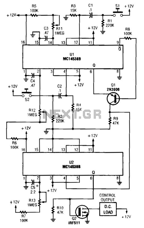
When switch SI is closed, pin 9 of operational amplifier U1 goes low, activating transistor Q1 for a predetermined duration. If switch S2 is closed during this time, transistor Q2 is activated for another predetermined duration. Resistors R1 and...
Timers are widely used in industrial and domestic applications for automating tasks. Microcontrollers can be used to design versatile and accurate timers. Timers play a crucial role in both industrial and domestic environments by facilitating the automation of various tasks....
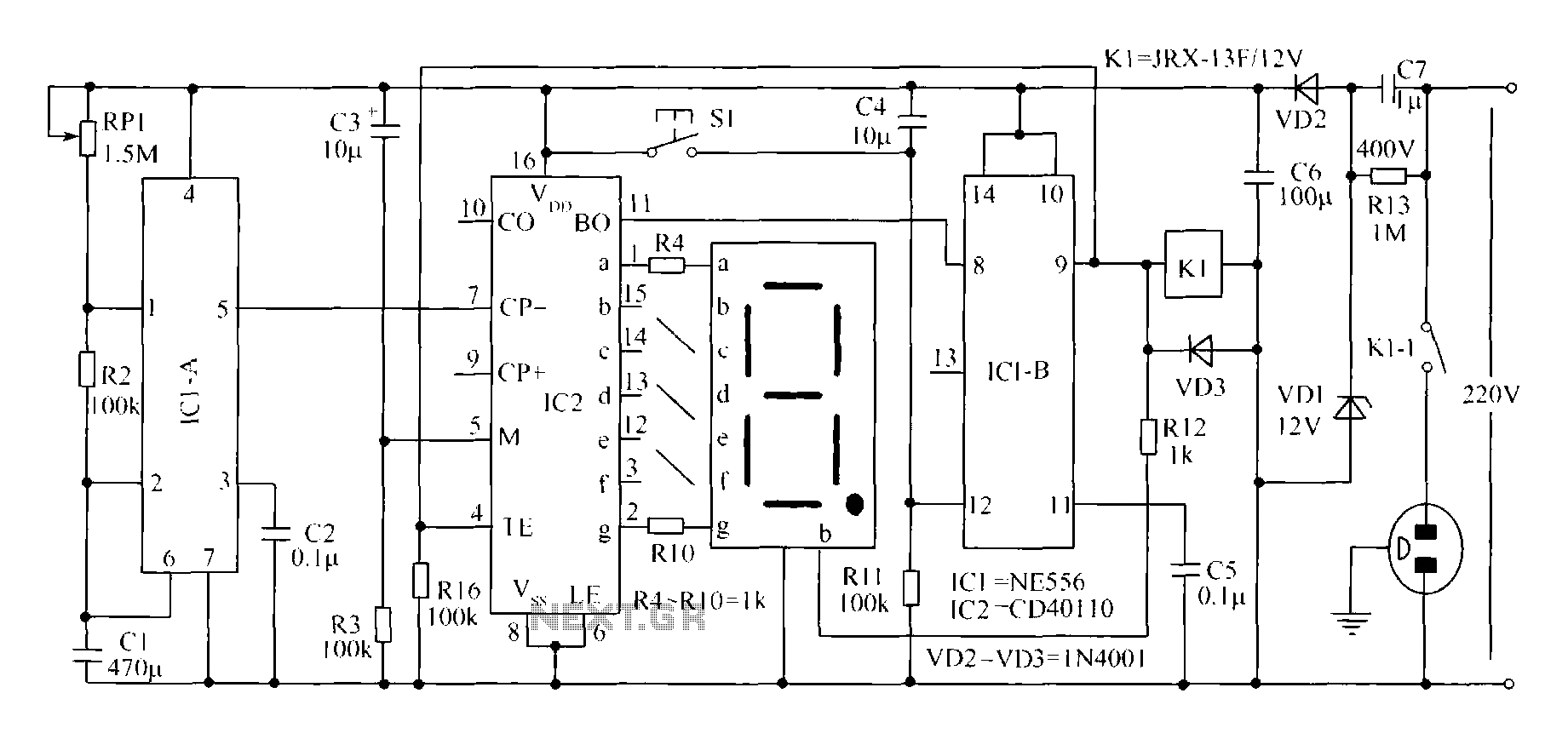
A novel timing switch circuit features a "Variable Timing" adjustment function in addition to a standard timing circuit. It also includes a countdown display feature, which indicates the remaining time of the timing circuit, making it particularly useful. The...
This is a lamp timer capable of operating two separate relay switches. Outputs can be in three (or restricted to two) states: OFF, delayed ON and constant ON. Delayed ON mode is indicated by the LEDs. The source code...
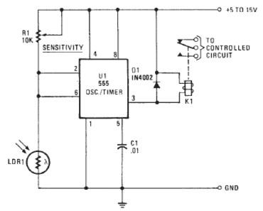
The following circuit illustrates a Photo Alarm Electronic Circuit. This circuit is based on the 555 Timer IC and incorporates features such as an LDR (light-dependent resistor). The Photo Alarm Electronic Circuit utilizes a 555 Timer IC configured in monostable...
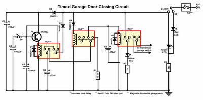
Timer garage door circuit schematic diagram, printed circuit board. The timer garage door circuit is designed to automate the opening and closing of a garage door based on a predetermined time interval. The schematic diagram illustrates the layout and connections...