
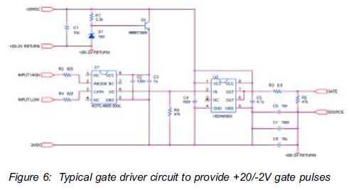
Control car horns in PWM

The circuit design involves a MOSFET driver capable of managing high current loads, specifically tailored for car horns. The MOSFET should be chosen based on its current rating, with a minimum threshold of 30A to accommodate peak demands. Thermal management is critical; therefore, a heatsink may be necessary to maintain operational temperatures within the specified limits. The PWM signal, generated by a microcontroller or dedicated PWM generator, modulates the gate of the MOSFET, allowing for precise control over the horn's volume and sound characteristics.
A snubber circuit, consisting of a resistor and capacitor in series, may be employed across the MOSFET to mitigate voltage spikes caused by the inductive load of the horn. This will enhance the reliability of the system and protect the MOSFET from potential damage. Additionally, the PWM frequency should be adjustable to explore the relationship between frequency and sound pitch, enabling further experimentation with sound modulation.
The circuit should also include a flyback diode in parallel with the horn to provide a path for the inductive kickback when the MOSFET is turned off, preventing damage to the MOSFET and ensuring system longevity. The overall design should prioritize efficiency, reliability, and thermal management to ensure optimal performance of the car horn system under varying operational conditions.The past experiences was pretty difficult, because the car horns have an inductive charge and it takes 12A and peak may be at 20 or 30A. The current electronic system is not reliable at all. It`s a lot of intensity. I need to dissipate 240W => 0. 3 x 240 = 72 °C. It is lesser than the temperature range maximum 150 °C, so it could work. Isn`t it Or I have to sum all other thermal resistances Rtheta HA and Rtheta CH An electronic engineer told me that I have to take the Volt factor. If I want to divide the voltage by 2 (6V), the MOSfet resists and has to dissipate : (12-6) * 20 A = 120 W.
That`s why I use the worst case, when the MOSfet resists to let pass only 0. 0001 V for example. It give me 240W. With PWM, you can play with the volume, some kind of artefacts (materials frictions) and sound distorsion (before and after). I realized that the car horn sound is the saturation. With PWM, I can play with this sound like an ADSR enveloppe in synthesis music. With differents enveloppes, we have different sounds. From : An electronic engineer told me that I have to take the Volt factor. If I want to divide the voltage by 2 (6V), the MOSfet resists and has to dissipate : (12-6) * 20 A = 120 W.
That`s why I use the worst case, when the MOSfet resists to let pass only 0. 0001 V for example. It give me 240W. I don`t know anything about "linear" (Ohmic) and saturation (active) modes. According to your note and the wikipedia article about MOSFET, it seems understable that below a threshold the mosfet acts like a resistor and after it is active, his resistance is equal to his Rdson. If I can put on/off (5V / 0V) the mosfet 500 times per second, the PWM frequency, it is below the threshold every 250 Hz, and it acts like a resistor very shortly, and with the 12V current.
And if I send in PWM only 0 logic signal, what happened. Is it a resistor May be the MOSfet is never in the linear mode, because. So I don`t know what conclude. I don`t know the relation between PWM frequency and the pitch. When you do the same thing with a speaker connected to a PWM output, you got pitch changing, but for now, I can`t control the horn horns, we control only the volume. 🔗 External reference
Related Circuits
The silicon carbide (SiC) MOSFET offers notable advantages, including a straightforward drive circuit. It possesses unique characteristics that render it a superior switching device in comparison to traditional options. The silicon carbide MOSFET is a type of field-effect transistor that...
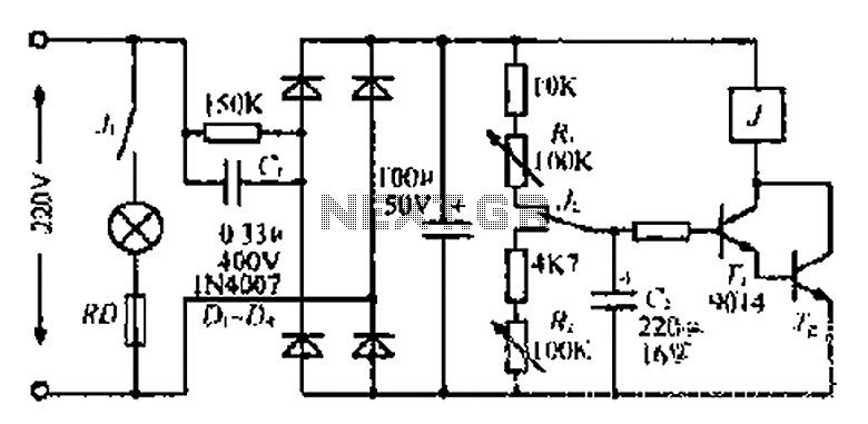
220V mains electricity is sent through a 0.33 µF capacitor (Ci) and a 50 kΩ resistive drop. A bridge rectifier composed of diodes D1 to D4 converts the AC voltage to DC. After passing through a 100 µF capacitor...
Connect a 12-volt, 20-watt lamp and a 12-volt battery to the circuit, ensuring correct battery polarity. Momentarily pressing and releasing the button will turn the lamp on. Repeatedly pressing the button will cycle through different power levels. Pressing and...

When a carrier signal is modulated using amplitude modulation, four frequency components are produced. The first component is the modulating signal itself, the second is the carrier frequency, while the last two are the sum and difference of the...
A switch that is controlled by its ambient temperature operates without human intervention, except during the assembly of the electronic thermostat. This thermally controlled switch has numerous practical applications. For instance, if the internal temperature of a computer rises...
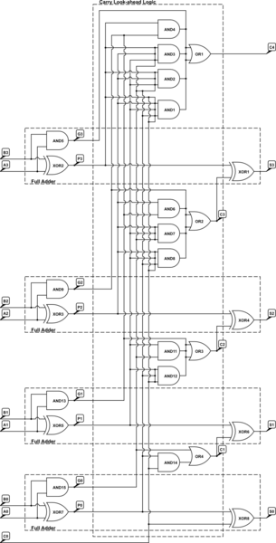
A 4-bit Carry Look Ahead Adder has 3 gate delays for all carry bits and 4 gate delays for all sum bits, whereas ripple adders have 7 and 8 gate delays, respectively. The 4-bit Carry Look Ahead Adder (CLA)...