
IR REMOTE CONTROL RECEIVER

The remote-control receiver circuit operates by receiving signals from a remote control device. The PIC16C54 microcontroller serves as the central processing unit, executing the control logic necessary for interpreting the incoming signals. It is capable of handling various tasks, including signal decoding, data processing, and controlling output devices based on the received commands.
The 93LC46 EEPROM is integrated into the system to provide non-volatile memory storage. This allows the microcontroller to retain configuration settings or other critical data even when power is removed. The three-line interface of the EEPROM consists of a clock line, a data line, and a chip select line, facilitating efficient communication between the microcontroller and the memory.
The schematic may also include additional components such as resistors, capacitors, and possibly a power supply circuit to ensure stable operation of both the microcontroller and the EEPROM. The design should account for power management to prolong battery life in portable applications. Additionally, appropriate filtering and decoupling capacitors should be employed to minimize noise and ensure reliable operation of the digital components.
Overall, this remote-control receiver schematic is designed for flexibility and efficiency, making it suitable for various applications in consumer electronics, home automation, and remote monitoring systems.A schematic diagram of the remote-control receiver is shown. The heart of the circuit is IC1, a PIC16C54 8-bit CMOS manufactured by Microchip. The microcontroller stores its data in IC2, a 93LC46 1-kbit serial EEPROM (electrically erasable programmable read-only ntemory), also manufactured by Microchip. In this application, the 93LC46 has a three-line inte.. 🔗 External reference
Related Circuits
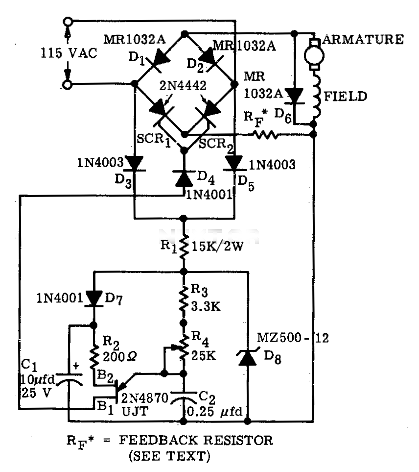
A bridge circuit consisting of two silicon-controlled rectifiers (SCRs) and two silicon rectifiers provides full-wave power to the motor. Diodes D3 and D5 deliver direct current (DC) to the trigger circuit through dropping resistors, R1. The phase delay of...
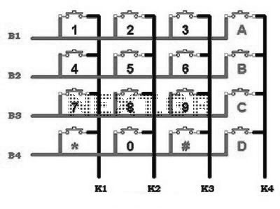
This includes an interface that is simple enough for mastery, as the keypad supports input facilities commonly used in Man-Machine Interface (MMI) applications. For example, various types of keypads can be found in the market. This discussion will focus...

The circuit is constructed using two 555 timer integrated circuits (ICs), designated as U1 and U2. U1 is configured as a variable duty cycle oscillator with a fixed time period of approximately 0.1 seconds. The duty cycle can be...
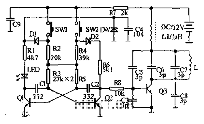
The circuit diagram illustrates a dual radio remote control switch system. The transmitter section features Q3, which generates a high-frequency carrier signal, while Q1 and Q2 form the oscillator circuit. Pressing switch SW1 results in an oscillation frequency of...
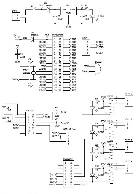
How to turn on equipment by sending SMS `1111` to switch it ON and switch off the equipment by sending SMS `0000`. The GSM switch will receive instructions for either load 1 (L1), load 2 (L2), load 3 (L3),...
This article is intended for complete beginners with servo motors. It provides an overview of the basic theory behind servo motors and offers detailed instructions on how to utilize them with AVR microcontrollers such as the ATmega32. Servo motors are...