
control relay with infrared circuit

The circuit operates on the principle of infrared light detection, providing a touchless control mechanism for various appliances. The IR LED1 continuously emits infrared light, which is typically invisible to the human eye. When a hand moves within the detection range, it interrupts the infrared beam, causing a change in the light intensity received by the phototransistor T1. This change is detected and processed by the operational amplifier (IC1), which is configured as a comparator. The output from IC1 is determined by the voltage levels at its inverting and non-inverting inputs.
The sensitivity of the circuit can be fine-tuned using the voltage-divider preset (VR1). Adjusting VR1 modifies the reference voltage at pin 2 of IC1, allowing for calibration based on environmental conditions or specific application requirements. This feature ensures that the circuit can adapt to varying levels of ambient light or distance of the hand from the IR LED1.
The transistor BC548 (T2) acts as a switch that controls the relay (RL1). When the output from IC1 goes high, it turns on T2, allowing current to flow through the relay coil. This energizes the relay, which closes its contacts and completes the circuit to the connected appliance. The relay serves as an isolating mechanism, ensuring that the low-power control circuit does not directly handle the high voltage of the appliance.
Overall, this circuit design provides a safe, efficient, and user-friendly solution for operating home appliances without the need for direct contact, significantly reducing the risk of electrical hazards.Normally, home appliances are controlled by means of switches, sensors, etc. However, physical contact with switches may be dangerous if there is any shorting. The circuit described here requires no physical contact for operating the appliance. You just need to move your hand between the infrared LED (IR LED1) and the phototransistor (T1). The inf rared rays transmitted by IR LED1 is detected by the phototransistor to activate the hidden lock, flush system, hand dryer or else. This circuit is very stable and sensitive compared to other AC appliance control circuits. It is simple, compact and cheap. Current consumption is low in milliamperes. The circuit is built around an IC CA3140, IRLED1, phototransistor and other discrete components. When regu lated 5V is connected to the circuit, IR LED1 emits infrared rays, which are received by phototransistor T1 if it is properly aligned.
The collector of T1 is connected to non-inverting pin 3 of IC1. Inverting pin 2 of IC1 is connected to voltage-divider preset VR1. Using preset VR1 you can vary the reference voltage at pin 2, which also affects sensitivity of the phototransistor. Op-amp IC1 amplifies the signal received from the phototransistor. Resistor R3 controls the base current of transistor BC548 (T2). The high output of IC1 at pin 6 drives transistor T2 to energise relay RL1 and switch on the appliance, say, hand dryer, through the relay contacts.
The working of the circuit is simple. 🔗 External reference
Related Circuits
The optical safety switch circuit includes a power supply circuit, a light control circuit, and a control implementation circuit (switch circuit). The power circuit is made up of a power transformer (T), a bridge rectifier (UR), and a filter...
The human eye is highly sensitive to visible light but cannot detect infrared (IR) radiation. This limitation can make it challenging to test or verify equipment that emits infrared radiation. An IR detector circuit has been developed to address...
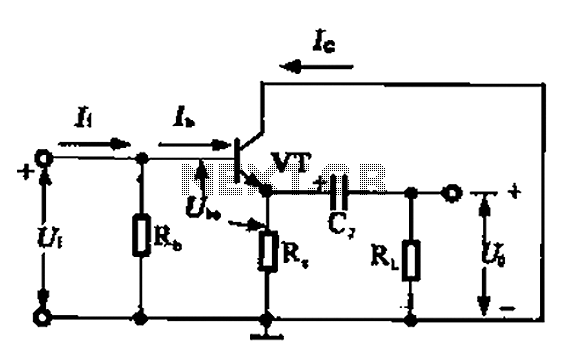
A common collector amplifier circuit can be analyzed through its DC and AC paths. The DC path provides a bias circuit for the power transistor, determining whether it is in an active or off state, primarily influenced by the...

WB5LUA described GaAsFET preamplifiers for several microwave bands, which included an active bias circuit for the GaAsFET. Although newer devices have been introduced that offer improved performance, they require different bias points with varying currents and voltages. Modifying the...
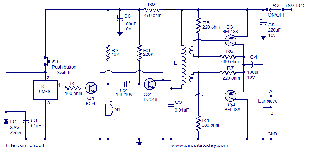
A straightforward intercom circuit designed using transistors. It does not require a changeover switch and can be used similarly to a telephone. This intercom circuit utilizes transistors to facilitate communication between two or more stations without the need for complex...

The TDA1519 circuit can deliver 2x6 watts of output power. The TDA1519 is an integrated class-B dual output amplifier housed in a 9-lead single in-line (SIL) plastic medium power package, primarily developed for car radio applications. The TDA1519 amplifier is...