
Control Voltage Distributor

This project involves the construction of a synthesizer circuit that leverages analog components to generate and manipulate audio signals. The design typically includes oscillators, filters, and envelope generators, which can be interconnected to create a wide range of sounds. The absence of detailed circuit descriptions and parts lists suggests that builders must possess a solid understanding of electronics, including familiarity with components such as capacitors, resistors, transistors, and integrated circuits.
The project may utilize standard synthesizer architectures, such as subtractive synthesis, where sound is generated by oscillators and then shaped by filters and modulation sources. Builders are expected to have knowledge of signal flow and the ability to troubleshoot common issues, such as unwanted noise or signal distortion. The lack of PCB layouts indicates that builders may need to create their own custom boards, requiring skills in PCB design and fabrication.
For successful implementation, it is crucial to have access to essential tools and equipment. An oscilloscope will aid in visualizing waveforms and debugging the circuit, while multimeters are necessary for measuring voltage, current, and resistance. Additionally, soldering tools and prototyping boards may be required for assembling the circuit components.
Given the complexity of the project, it is advisable for builders to engage in thorough research and possibly seek out supplementary resources, such as online forums or instructional videos, to enhance their understanding of synthesizer design and construction. Overall, this project offers a valuable opportunity for experienced electronics enthusiasts to explore the intricacies of synthesizer technology while contributing to the DIY community.This project is an older design and has most likely been superceded by a newer one. However, it is still a viable design and useful for your home-brew synth. Sorry but most of these do not have circuit descriptions, parts lists or PC board layouts (They really put the `Y` in DIY). The designs are here for individual and educational use only and no permission is given for large scale production for sale. This is an intermediate to advanced project and I do not recommend it as a first project if you are just getting started in synths or electronics. Only the circuit and some explanation are shown here. A lot of project building, troubleshooting and electronics experience is assumed. Additionally, electronic equipment ownership (scope, meters, etc. ) is taken for granted. If you are interested in building this project please read the entire page before ordering PC boards to ensure that the information provided is thorough enough for you to complete the project successfully.
🔗 External reference
Related Circuits
Based on the classic Baxendall tone control circuit, this provides a maximum cut and boost of around 10dB at 10K and 50Hz. The first BC109C transistor (left hand side) is acting as a buffer. It provides the circuit with...
Faulty readings from the DS18B20 temperature sensors used in tank thermometers were likely caused by the waterproofing method involving heat shrink and silicone. This situation provided an opportunity to enhance the code for better tolerance against erroneous readings. The...
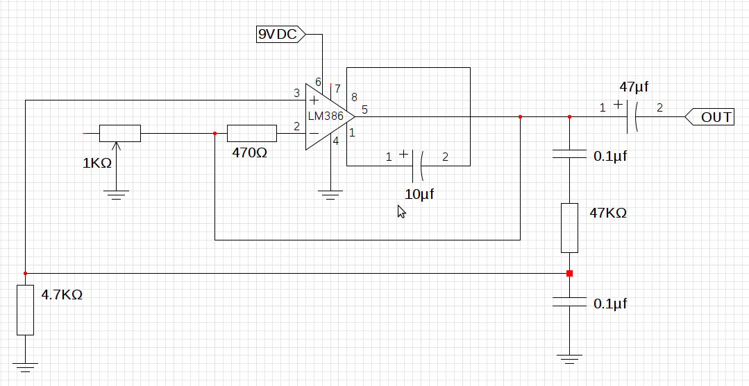
The design utilizes the LM386n-1 integrated circuit, powered by a single power supply to maintain a compact layout. There is a need to control the frequency, and the user is inquiring about which component values should be adjusted for...
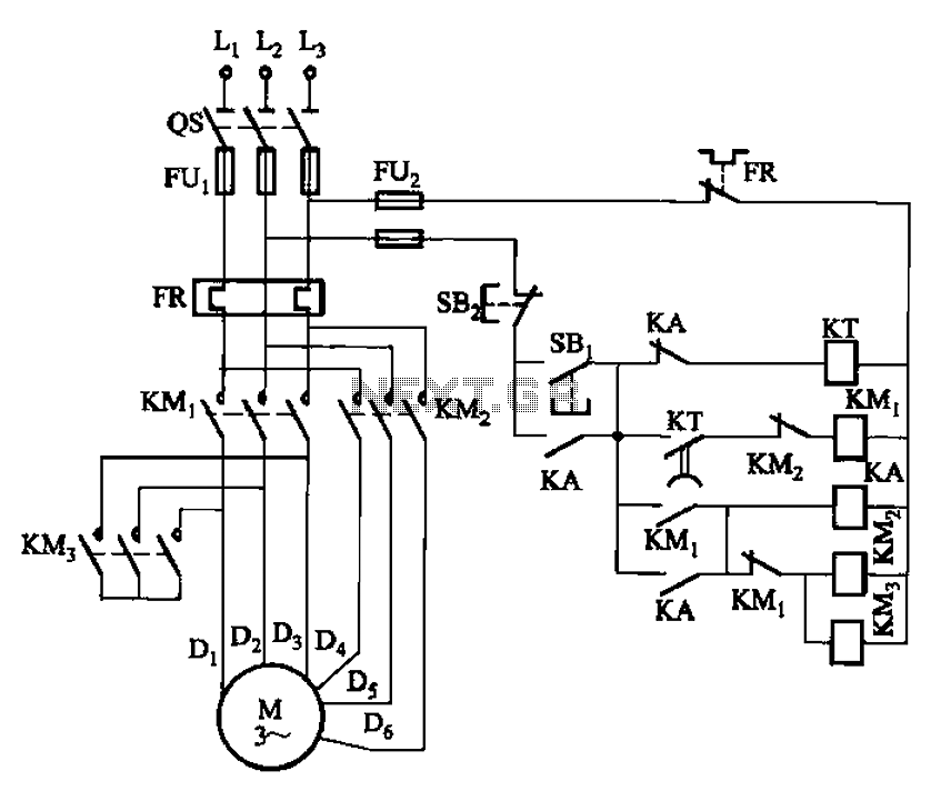
The circuit depicted in Figure 3-99 illustrates a low start-up mechanism for a motor, which transitions to high-speed operation automatically. The start-up process is facilitated by a shaped connection, while the transition to high-speed operation is managed by a...
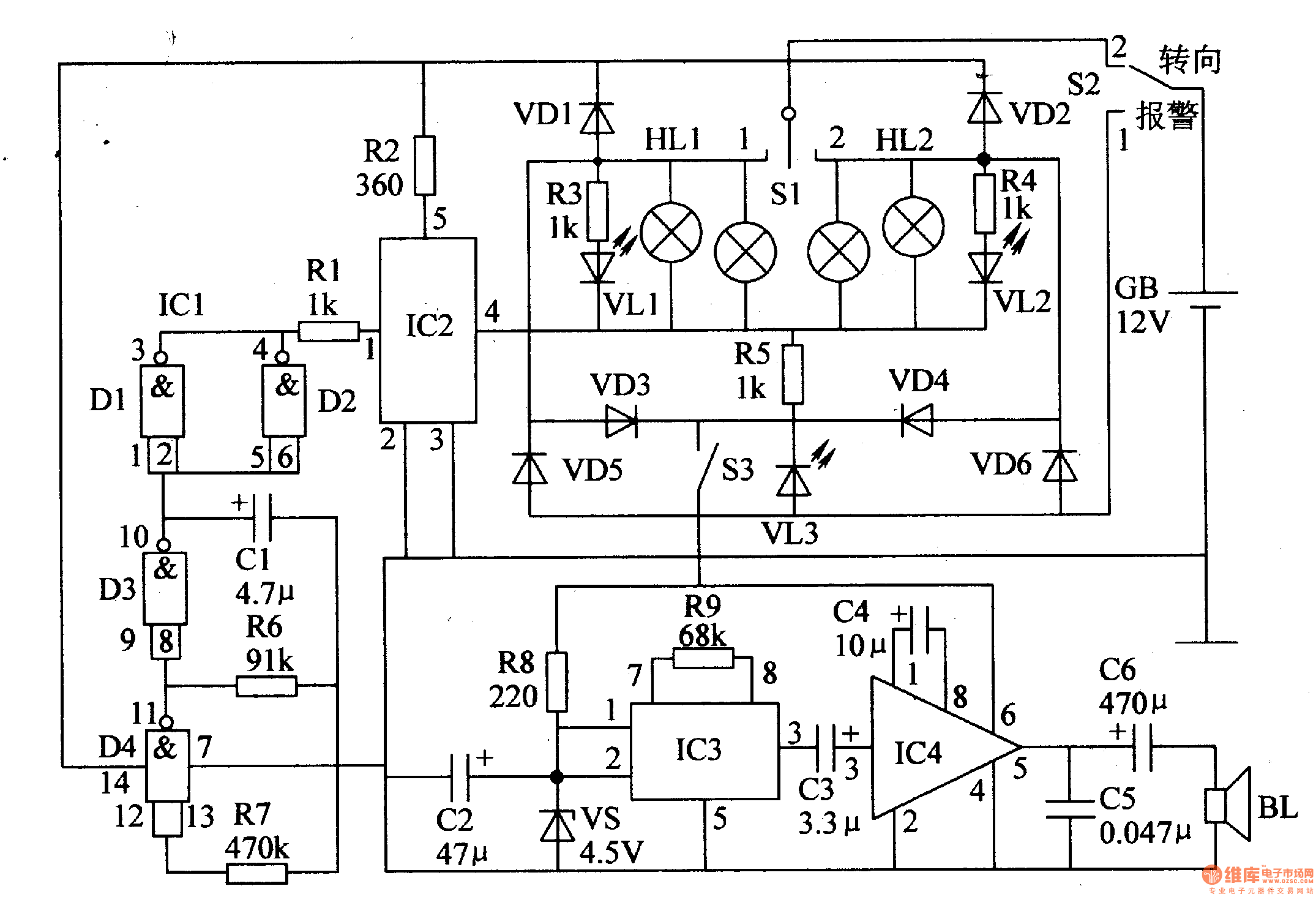
The circuit comprises a low-frequency oscillator, an electronic switch circuit, a control circuit, a photoelectric display circuit, and a music alarm circuit. The low-frequency oscillator is constructed using an integrated circuit (IC) with internal NAND gates and external resistor-capacitor...
The page is about equipping an Atmel AVR microcontroller based system with a Prism WLAN interface. This document is intended for people that already have experiences with the AVR microcontrollers and teaches them how to add a cheap but...