
Converting current to voltage transducer circuit Using LM107
The described circuit operates as a current-to-voltage transducer, effectively converting input current into a proportional output voltage while minimizing measurement errors. The input current (IIN) is directly applied to a summing node, which is a key feature of this configuration. This node is typically part of an operational amplifier (op-amp) setup, where the characteristics of the op-amp play a crucial role in the overall performance of the transducer.
In this circuit, resistor R1 is employed to set the scale factor, establishing a direct relationship between the input current and the output voltage. The output voltage (VOUT) can be expressed mathematically as VOUT = IIN * R1, indicating that for every ampere of input current, the output voltage increases by R1 volts. This linearity is essential for accurate signal processing in various applications, including sensor interfacing and data acquisition systems.
The presence of Ibias, the input bias current of the operational amplifier, introduces a minor error in the output voltage. This bias current is summed with the input current, which can lead to deviations from the ideal output. However, in well-designed circuits, this error can often be minimized through careful selection of components and circuit layout, ensuring that the impact of Ibias is negligible in the overall performance.
Overall, this current-to-voltage transducer circuit is a reliable solution for applications requiring precise current measurements, providing a linear output voltage that can be easily interfaced with analog-to-digital converters or other signal processing components. The design considerations surrounding the choice of resistor values, op-amp specifications, and layout techniques are critical for achieving optimal performance and accuracy in practical implementations.Converting into voltage is undesirable for two reasons: first, an impedance is inserted into the measuring line causing an error; second, amplifier offset voltage is also amplified with a subsequent loss of accuracy. The use of a current to voltage transducer avoids both of these problems. This is current to voltage transducer circuit. The input c urrent is fed directly into the summing node and the amplifier output voltage changes to extract the same current from the summing node through R1. The scale factor of this circuit is R1 volts per amp. The only conversion error in this circuit is Ibias which is summed algebraically with IIN. Here is a schematic drawing : 🔗 External reference
Related Circuits
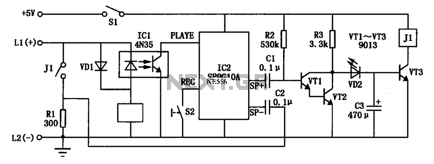
An automatic telephone responder circuit is illustrated. It incorporates a 10-second voice recording circuit (SR9G10A) activated by the power switch (S2). The circuit utilizes an electret microphone (IC2) for sound input. To initiate the response, the user must press...

A GdS cell serves as one leg of a bridge circuit. Potentiometer R6 in another leg establishes the trip point. Potentiometer R5 allows for hysteresis adjustment to prevent chattering or hunting of the relay. The light level must increase...
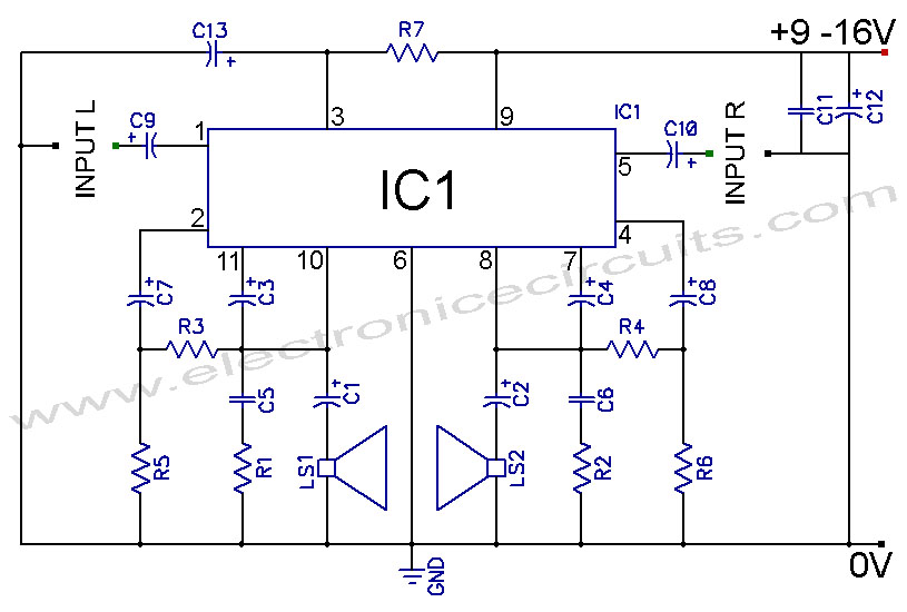
TDA2004 Car Battery 12W Stereo Amplifier Circuit. Its main features are low distortion, low noise, and high reliability of the chip. The TDA2004 is a highly integrated audio amplifier designed specifically for automotive applications. This circuit is capable of delivering...
This page provides basic information about voltage comparator integrated circuits and is to act as reference material for other circuits. The circuits shown are based on the LM339 Quad Voltage Comparator chip or the LM393 Dual Voltage Comparator chip....
There have been several requests for a quiz circuit, leading to the development of a four-input design that can be easily modified. This design utilizes four integrated circuits (ICs) and features four input circuits, four independent outputs, and a...
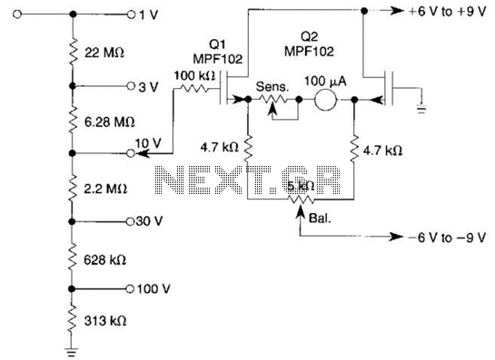
This voltmeter utilizes a pair of JFETs in a balanced-bridge source-follower amplifier circuit. Q1 and Q2 should be matched within 10% for IDSS. This configuration minimizes meter drift and maintains bridge balance over temperature. The described voltmeter is an advanced...
Warning: include(partials/cookie-banner.php): Failed to open stream: Permission denied in /var/www/html/nextgr/view-circuit.php on line 713
Warning: include(): Failed opening 'partials/cookie-banner.php' for inclusion (include_path='.:/usr/share/php') in /var/www/html/nextgr/view-circuit.php on line 713