
Sound Controlled Activated Triggered LED

The circuit operates by utilizing a microphone to sense sound levels. When a sound exceeds a predetermined threshold, the microphone generates a corresponding electrical signal. This signal is then processed by the charge pump section, which is designed to increase the voltage to a level sufficient to power the LED.
The charge pump consists of several critical components. The 100nF capacitor is used for energy storage, allowing the circuit to maintain a stable output voltage during operation. The 10kΩ resistor serves to limit the current flowing through the microphone and the subsequent components, ensuring that the microphone operates within its safe limits and preventing damage.
The signal diode plays a crucial role in directing the flow of current within the circuit. It allows current to flow in one direction while blocking it in the opposite direction, which helps to prevent backflow that could damage the circuit components. Additionally, the uF capacitor (the exact value should be specified for precise functionality) further stabilizes the output voltage, smoothing out any fluctuations that may occur during operation.
When the microphone detects a loud sound, the generated signal activates the charge pump, which in turn powers the LED. This visual indicator serves as an alert, signaling that a loud sound has been detected. The circuit can be applied in various applications, such as sound level monitoring systems, alarms, or audio equipment to provide visual feedback on sound levels. Proper selection of components and their values is essential to ensure responsive and reliable operation of the circuit.When the microphone detects a loud sound, this circuit will turn the LED on. The `charge-pump` section consists of the 100n, 10k, signal diode and uF.. 🔗 External reference
Related Circuits
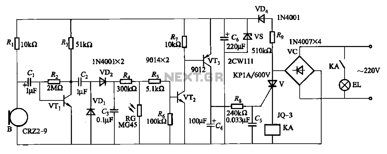
A resistor R8, capacitors Cd, and a thyristor V AC switch form a delay circuit. The lamp's lighting delay time is determined by the resistor Rs and capacitor C4, with a delay of approximately 40 seconds as indicated in...
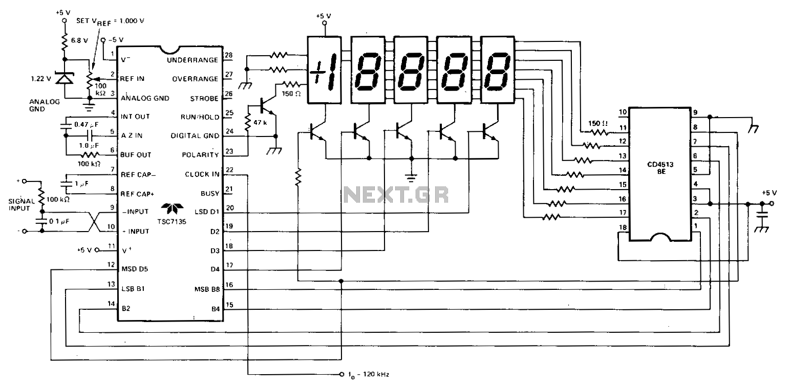
A Teledyne TSC7135 digital voltmeter (DVM) chip is utilized to control a multiplexed 5-digit display. To facilitate common cathode drive, a CD4513BE CMOS integrated circuit (IC) functions as a segment driver, with selection controlled by pins 17-20 of the...
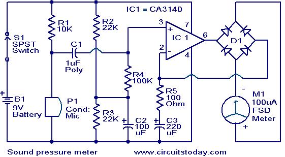
This circuit is a simple sound level checker, useful for setting up home theater systems by testing sound pressure levels across different channels and positions in a room. The design features a non-inverting amplifier utilizing the CA 3140 operational...
A pulsating light is used for signaling purposes with a voltage of 230V. A simple circuit has been designed, consisting of an LED diode, two capacitors, two resistors, a diac, and a diode. The operation of the circuit is...
Most PC enclosures provide only a single LED to indicate hard disk access, which is connected to the motherboard via a two-pin connector. However, this LED only functions with IDE drives, and if a SCSI disk controller is installed,...
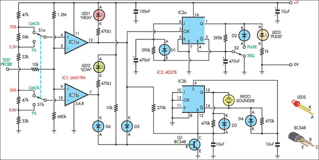
This logic probe can be selected to operate on TTL or CMOS logic levels, depending on switch S1. A string of resistors associated with switch S1 sets the threshold levels for a window comparator comprising IC1a and IC1b. Depending...