
Count Down Timer Circuit

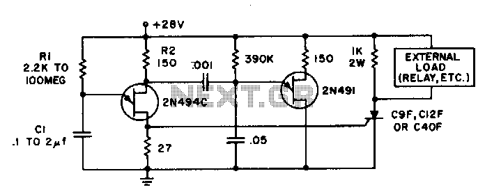
In this circuit configuration, the switch SI is utilized to control the overall power supply to the system. When SI is in the off position, it allows the battery voltage to charge the timing capacitor CI. This capacitor plays a crucial role in maintaining the power state of the circuit, as it provides a temporary power source that can keep certain components inactive while preventing power from flowing to the rest of the circuitry.
Transistor Q1 serves as the main control element in this setup. When capacitor CI is charged, it ensures that Q1 remains in an off state. This state is critical, as it prevents the subsequent transistors Q2, Q3, and Q4 from turning on. These transistors are likely configured in a cascading manner, where the state of Q1 directly influences the operation of Q2 through Q4.
The design implies that the timing capacitor CI is selected based on the desired delay or timing characteristics required for the application. The charging time of CI will dictate how long the circuit remains inactive before any further action can take place. This aspect is crucial in applications where a delay is necessary before activating the main circuitry, allowing for controlled startup sequences or power management.
Overall, this circuit demonstrates a simple yet effective method for controlling power distribution within an electronic system, leveraging the properties of capacitors and transistors to achieve desired operational states without unnecessary power consumption. With switch SI in the off position, as shown, battery voltage is applied across timing-capacitor CI, which stays charged while the rest of the circuitry has no power supplied to it. Transistor Ql, and thus transistors Q2 through Q4, are kept in an off condition as long as CI has a sufficient charge.
Related Circuits
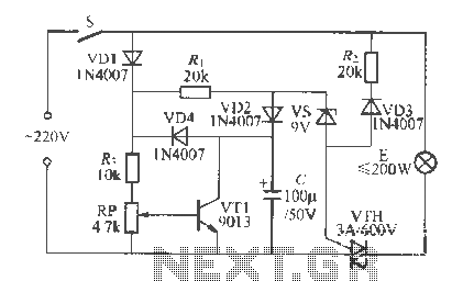
Time delays ranging from 0 milliseconds to over three minutes can be achieved with this circuit without the need for tantalum or electrolytic capacitors. The timing interval begins when power is applied to the circuit. At the conclusion of...
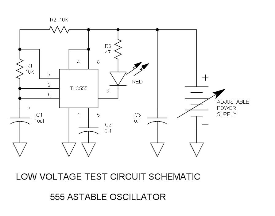
How many individuals have experienced legitimate issues with the 555 timer? It can be inferred that these problems often involve the reset line, specifically pin 4, which must be set high before operation. The 555 timer IC is a versatile...
Controlled by indoor and outdoor temperature, this circuit features a simple and highly reliable design. It is intended to control a heating system or central heating plan. The described circuit functions as a temperature control system, integrating both indoor and...
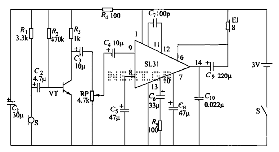
This is a type of connection switch designed for incandescent lamps, known as a spider life extension switch. It has two main functions: First, it utilizes electroporation to enable semi-crossing buck starts and fully preheats the filament to transfer...
Bicycle tire leak detector circuit schematic. The circuit detects air leaks in car tires caused by sharp objects. It uses a microphone (BM) to capture the sound of escaping air, which is then converted into an electrical signal. This...
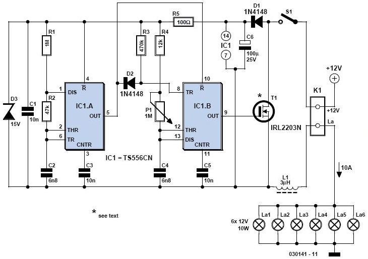
A light dimmer is quite uncommon in a caravan or on a boat. This document outlines how to create one, allowing for mood adjustment when needed. A light dimmer circuit is an essential component for enhancing the ambiance in confined...