
Quirky 555 Timer Reset Function

The 555 timer IC is a versatile device widely used in various electronic circuits for timing, pulse generation, and waveform shaping. It operates in several modes, including monostable, astable, and bistable configurations. One common issue that users encounter is related to the reset functionality, which is controlled by pin 4 of the IC.
In the standard 555 timer configuration, pin 4 serves as the reset pin, which allows for the interruption of the timing cycle. For proper operation, this pin must be held high (typically connected to Vcc) to ensure that the timer can function correctly. If pin 4 is inadvertently pulled low, the timer will reset, causing the output to go low regardless of the state of the other input pins. This behavior can lead to unexpected results in circuits where precise timing is critical.
To mitigate issues associated with the reset line, it is advisable to include a pull-up resistor connected to pin 4. This resistor ensures that the reset pin maintains a high state unless intentionally driven low by an external signal. Additionally, careful attention should be given to the layout of the circuit to minimize noise and interference that could inadvertently affect the reset line.
In summary, while the 555 timer is a robust and widely used component in electronic design, attention to the reset functionality is crucial for reliable operation. Properly managing pin 4 can prevent common issues and enhance the overall performance of circuits utilizing this versatile timer IC.How many have had legitimate problems with the 555 timer? Let me guessit involved the reset line, did it not? We all know that pin 4 must be set high befo.. 🔗 External reference
Related Circuits
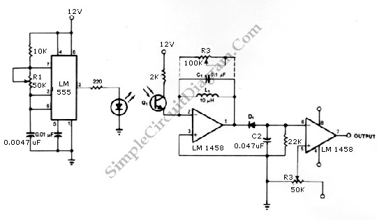
The infrared transmitter and receiver circuit depicted in the schematic diagram below can function as a remote control. The transmitter primarily operates as an oscillator. The infrared transmitter and receiver circuit is designed to facilitate wireless communication through infrared signals,...
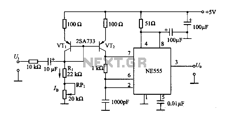
The circuit consists of a NE555 timer and a frequency modulation circuit that modifies the self-excited multivibrator NE555 by adjusting the charging current for frequency modulation. The components VT1 and VT2 form a current mirror circuit, which generates a...
This circuit is designed to power a lamp or other appliance for a specified duration of 30 minutes, after which it automatically turns off. It is particularly useful for nighttime reading, as it can turn off a bedside lamp...
Pulse position modulation is similar to pulse width modulation, but the frequency is not constant. Like pulse width modulator circuit, pulse position modulation... Pulse Position Modulation (PPM) is a modulation technique in which the position of a pulse within a...
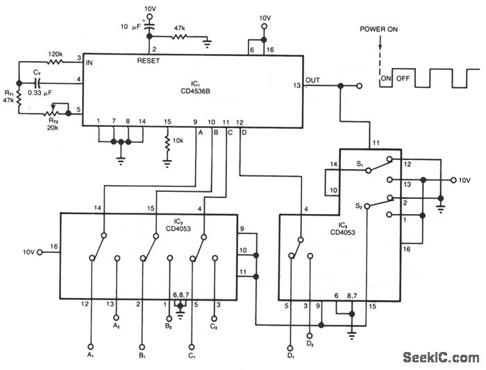
The timer circuit provides independent control of the output's on and off intervals, which can range from 0.055 seconds to 30 minutes, with minimal impact from power-line transients. IC1 is a CMOS programmable timer chip that features 24 ripple-binary...
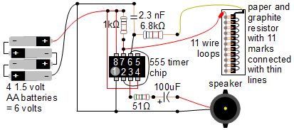
A simple music instrument/keyboard is created using a 555 timer chip circuit, a piece of paper, and a pencil. The project includes a more advanced automatic music player that utilizes a playing head and a long sheet of paper...