
Coupler Crystal Radio

The two-circuit tuner circuit design effectively demonstrates the principles of selectivity and sensitivity in radio reception. The architecture allows for fine-tuning through the use of variable capacitors and multiple taps on each coil, enhancing the user's ability to isolate specific frequencies. The use of ABS pipe for coil construction ensures durability while maintaining a lightweight structure. The choice of 22-gauge magnet wire is appropriate for minimizing resistance and ensuring efficient signal transfer.
The mechanical arrangement of the slider device for the secondary coil is a notable feature, promoting ease of adjustment and precision in tuning. The horizontal screw mechanism allows for incremental adjustments, which are critical for achieving optimal reception. The design encourages the user to engage with the tuning process actively, fostering a deeper understanding of radio frequency manipulation.
Furthermore, the inclusion of locking nuts for the lead screw enhances operational stability, preventing unintended movement during adjustments. The overall layout of the circuit, including the strategic placement of components and the systematic arrangement of taps, reflects a thoughtful approach to circuit design that prioritizes functionality and user experience.
In practical application, the tuner is versatile enough to be integrated into various radio sets or used independently, making it a valuable tool for amateur radio enthusiasts and professionals alike. The detailed instructions for assembly and testing provide a comprehensive guide for users, ensuring successful implementation and operation of the circuit. This design exemplifies the balance between complexity and usability, making it an exemplary model in the field of radio engineering.A two-circuit tuner, as the loose coupler, is one of the only ways selectivity can be accomplished without sacrificing sensitivity. Let`s look at the circuit, see figure #8: The signal is introduced to the primary antenna section via SW-1 arrangement, in which the antenna can be matched to the circuit with 12 taps on Coil L-1.
Coil L-1 is also tuned with the 365 variable across the entire L-1, which is a stationery coil. The secondary detector section, L-2 is a moving coil designed to slide in and out of the primary coil. See Figure #1 & #2 and you`ll note that the secondary coil is mechanically arranged on a slider device, which is moved by a horizontal screw arrangement.
The coil L-2 is also tuned by another 365 variable and another 12 taps to the detector/phones section. To summarize: The two tuned coils with 12 taps each and the variable coupling ability, give this receiver an extreme versatility in it`s ability to separate stations.
Winding and constructing the coils is quite time consuming and important to be correct. The primary, L-1 is wound on a 3 I. D. x 3-1/2 piece of ABS pipe. The 12 taps are every 4th. Turn and are on the inside of the coil. Leave the tap wires long enough to terminate to the rotary switch, which mounts at the end of the coil. I secured the taps, toward the switch-end of the coil with hot glue. It is important that the taps run along the wall of the inside of the coil form, to minimize interference with L-2 sliding in-and-out.
Make certain that both coils are wound in the same direction and that the ground-end matches each coil arrangement. L-2 is wound on a 2 I. D. x 3-3/4 piece of ABS pipe and constructed in the same manner as L-1. Each coil is wound with 22-gauge magnet wire and divides the taps points equally, for each coil. See figure`s # 1 through 4, which illustrates the mechanics of the coil/slider assembly. This assembly can be used independently of the entire set if you desire to use on another set, or simply for an antenna tuner.
I thought the lead-screw for moving the secondary was a nice twist and when testing the set, found it to be useful as this setting can be quite critical, at times. The handle on the lead-screw is a wooden toy wheel with an axle pin for the crank handle. The two nuts that secure the lead-screw under the primary coil should be locking nuts and adjusted sot the screw moves freely.
Testing the circuit: Connect a good antenna and ground, set the switches at position #6 and move the secondary towards the primary so it is just beginning to move inside. Connect a good set of phones to the phones terminals and use your best diode for the detector. Set the antenna variable to mid-range and slowly rote the detector tuning, denoting the stations heard.
Moving the secondary coil further into the secondary will increase the volume and decrease the sensitivity. The detector-select switch will increase the volume towards #1 and decrease toward #12. The same applies to the antenna switch and practice will show the best settings for your antenna/ground and area situations.
Have Fun, and until next time! Mike. 🔗 External reference
Related Circuits
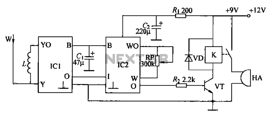
A circuit for an inductive burglar alarm is derived from a radio scanning detection circuit, which includes a signal processing circuit and an alarm circuit. The radar detection circuit module consists of components such as microwave emission, low-pass filtering,...
An RF field indicator is needed to verify power stages and transmitter antennas. This radio field indicator allows for the measurement of radiated energy from antennas. An RF field indicator is a crucial device in the field of telecommunications and...
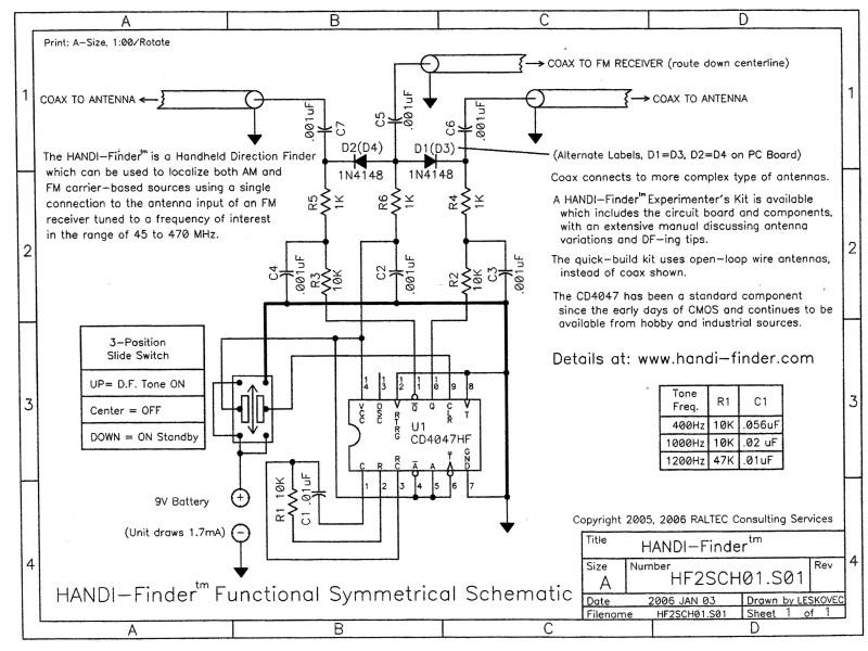
The HANDI-Finder is a handheld direction finder designed to localize both AM and FM carrier-based sources. It operates by connecting to the antenna input of an FM receiver tuned to frequencies between 45 and 450 MHz. This device emphasizes...
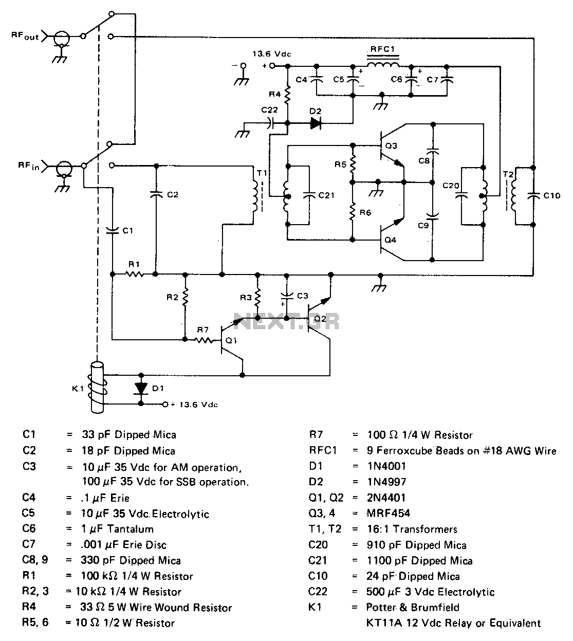
This inexpensive, easy-to-construct amplifier utilizes two MRF454 devices. It is specified for an 80 W power output with a 5 W input drive at a frequency of 30 MHz and operates on a 12 V DC supply. The amplifier circuit...
The FV-1 features internal circuitry that supports an external crystal, ideally a 32.768 kHz watch crystal. These crystals are very affordable and readily available. While other frequencies are available, they are not as cost-effective or common. If the system...
Crystal radios do not require external power sources to operate; they rely solely on radio waves. The first crystal set constructed was a "variometer" radio, which features a larger coil that slides over a smaller coil to modify the...