
Radio Field Indicator Circuit

An RF field indicator is a crucial device in the field of telecommunications and broadcasting. It is designed to measure the strength of radio frequency (RF) fields emitted by antennas, which is essential for ensuring the proper functioning of power stages and transmitter systems. The device typically operates by detecting the electromagnetic radiation produced by antennas when they transmit signals.
The RF field indicator usually consists of several key components, including an antenna, a signal processing unit, and a display unit. The antenna is responsible for capturing the RF signals in the vicinity, while the signal processing unit filters and amplifies the received signals to provide accurate measurements. The display unit presents the measured values, often in terms of voltage, power density, or field strength, allowing technicians to assess the performance of the antenna system.
Calibration of the RF field indicator is vital for ensuring accurate readings. This process involves comparing the device's measurements against known standards or reference values. Regular calibration helps maintain the reliability of the indicator, which is essential for compliance with regulatory requirements regarding RF exposure and safety.
In practical applications, the RF field indicator is employed during the installation and maintenance of antennas to verify that they are operating within specified parameters. It assists in identifying potential issues such as signal interference, improper alignment, or inadequate power levels. By providing real-time feedback on RF field strength, the indicator enables technicians to make informed decisions regarding adjustments and optimizations to the antenna system.
Overall, the RF field indicator is an indispensable tool in the telecommunications industry, ensuring that antennas operate efficiently and safely while adhering to regulatory standards.A rf field indicator is required to verify power stages and transmitters antennas. With this radio field indicator you can measure radiated energy from ant.. 🔗 External reference
Related Circuits
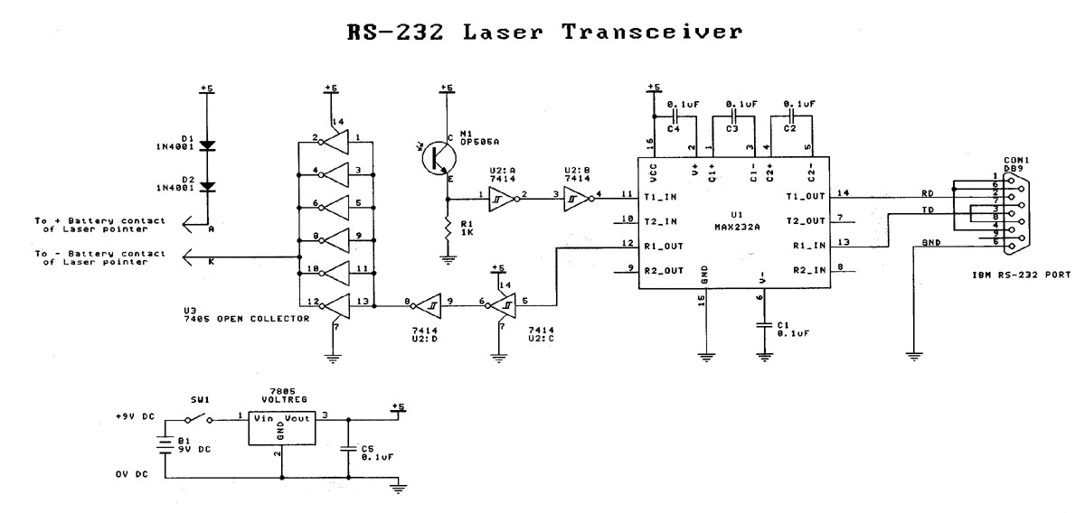
Laser based projects used to be expensive, until the development of solid state lasers. This project is designed for the entry level laser experimenter. The circuit allows any two computers with serial (RS-232) communication capability to communicate over 200...
Superheterodyne receivers have been mass-produced since around 1924, but for reasons of cost did not become successful until the 1930s. Superheterodyne receivers represent a pivotal advancement in radio technology, characterized by their ability to convert high-frequency signals into lower...
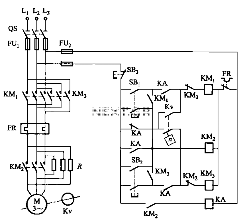
The circuit shown in Figure 3-129 is the C650-2 lathe brake control circuit, utilizing a speed control relay. The C650-2 lathe brake control circuit is designed to manage the braking mechanism of a lathe machine effectively. This circuit incorporates a...
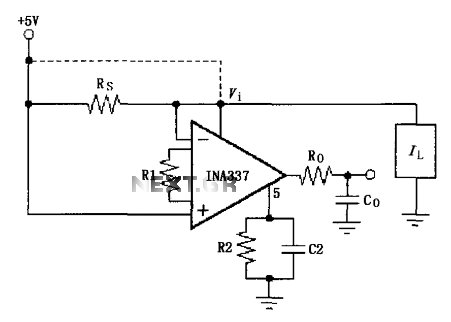
The INA337 circuit, as illustrated, is part of a load current measuring shunt circuit. It generates a voltage drop across the sampling resistor Rs, which is connected in series between the power source and the load. The load current...
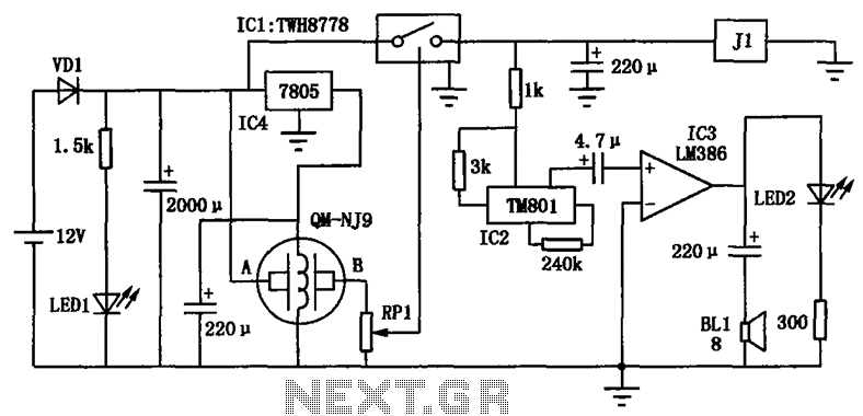
The alcohol detection alarm controller circuit is illustrated in the figure. It utilizes the QM-NJ9 alcohol gas sensor, which detects the presence of alcohol vapors. When alcohol is detected, the resistance between the AB-QM-NJ9 decreases, causing the wiper of...
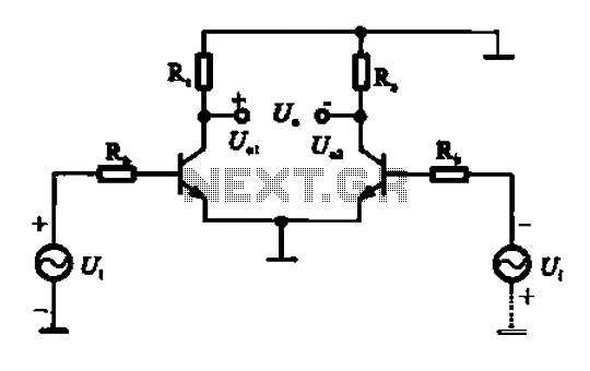
An amplifier circuit is designed to handle an assumed input consisting of two equal and opposite polarity signals, known as a differential mode signal. The two tube collector currents, Ic and IC7, are balanced in such a way that...