
CPF LOGGER Lite Simple DIY Data Logger for CPFers

The circuit in question relates to a timer calibration project that has undergone several revisions based on user feedback and operational requirements. The initial schematic was updated to reflect a crucial connection change where the transmission (TX) line was correctly routed to serial port pin 2, aligning with standard practices for serial communication protocols. This adjustment is significant as it ensures proper data transmission and reception between the microcontroller and external devices.
The transition to circuit version 1.0a indicates a formal acknowledgment of the correction and serves to maintain clarity within the documentation. The inclusion of the "10a" suffix in the file names helps in version control, making it easier for users to identify the most recent and accurate schematic.
Furthermore, the release of circuit version 1.1, described as a maintenance change, suggests that additional refinements have been made to enhance the overall performance or reliability of the circuit. Maintenance changes typically involve minor updates that do not alter the core functionality but improve aspects such as component selection, layout optimization, or noise reduction.
Users are encouraged to refer to the complete thread for comprehensive details regarding timer calibration techniques and other insights shared by contributors. This collaborative approach enhances the understanding and implementation of the circuit, ensuring users can effectively utilize the design in their projects.edit - There are information not included in this main post. Read through the thread for more information on timer calibration and other useful information by cpfers. - PEU pointed out the TX to be connected to serial port pin 2 instead of 3. This now corrected as circuit ver 1.0a and reflected in this main post. The respective file names are changed with ""10a"" surfix. - Slightly modified circuit version 1.1 is posted in the new post below. This is a maintenance change. Circuit files.. 🔗 External reference
Related Circuits
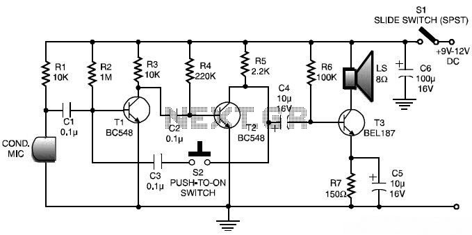
This is a low-cost and simple intercom circuit design. Some intercom circuits are built using integrated circuits. The circuit described here utilizes three readily available transistors that can be easily found in electronic stores. Even a novice can assemble...
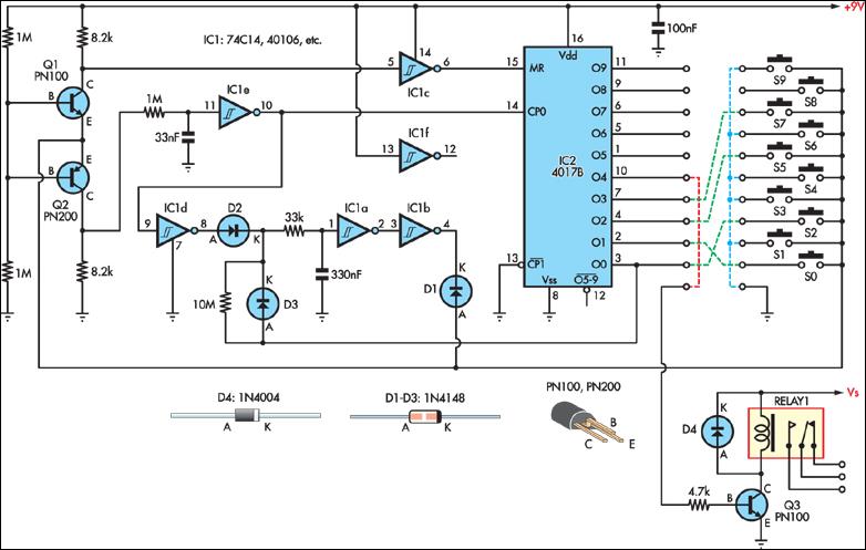
This simple combination lock accommodates codes from 1 to 9 digits long, with the only restriction being that the same digit cannot be used twice. The circuit is designed for a 4-digit code, illustrated by the example "2057". Any...
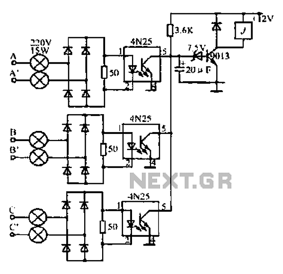
A, B, and C are used for a large power split-phase system. The A + BC range generator phase line features an A-A indole path string containing two 220V/15W bulbs. The bulbs recover based on macro instructions from J...
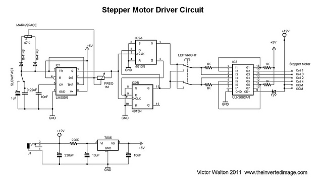
The commonly used 555 timer is configured for a variable mark/space ratio, which is essential for this application. Additionally, two D-type flip-flops (4013) are employed to provide the necessary count for the ULN2003 stepper motor driver. ULN2003 components may...

This circuit is sensitive to low-frequency electromagnetic radiation and can detect hidden wiring or the field surrounding a transformer. A radial type inductor is used as a probe, which effectively responds to low-frequency changing magnetic and electric fields. Ordinary...
A sine wave carrier is required for a magnetic transponder system. Various crystal-based oscillators, such as the Pierce oscillator, can be complex to design and ensure proper functionality. An alternative approach involves using a square wave oscillator in conjunction...