
Cricket Generator by 2N4891

The circuit design utilizes a combination of resistors and capacitors to create a sound generator that emulates the chirping of crickets. The primary components involved in this circuit are R3, C1, R5, and C2, each playing a crucial role in determining the frequency and modulation of the sound output.
Resistor R3 functions as a variable resistor, allowing for the adjustment of the circuit's resistance and thereby influencing the overall frequency of the sound produced. The capacitor C1 works in conjunction with R3 to set the timing characteristics of the oscillation. By altering the capacitance of C1, the time constant of the RC network can be modified, resulting in changes to the pitch and rhythm of the chirping sound.
Resistor R5 and capacitor C2 are also integral to the circuit's performance. R5 can be used to fine-tune the amplitude of the sound output, while C2 may serve to filter or smooth the signal, reducing unwanted noise and ensuring a clear sound reproduction.
To achieve the desired sound modulation, careful calculations and adjustments of these components are necessary. The interaction between the resistors and capacitors creates a unique sound signature, allowing for a wide range of cricket-like chirps. This circuit can be integrated into various applications, such as sound effects in toys or as part of a nature simulation device, providing an engaging auditory experience.This circuit gives sound handful that modifies interestedly, occurrence sound rate cricket Fixed. By R3 should experience change the value C1,R5 and C2.. 🔗 External reference
Related Circuits
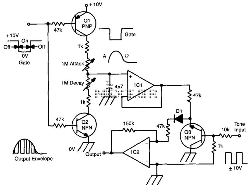
A gate voltage is applied to initiate the process. When the gate voltage is in the ON state, Q1 is activated, and capacitor C is charged through the attack potentiometer in series with the 1 kΩ resistor. By adjusting...
This circuit utilizes an EXAR XR2206 to generate sine, square, and triangular waveforms ranging from Hz to 100 kHz. The XR2206 chip (U1) is responsible for waveform generation, with resistor R7 regulating the frequency. Resistors R55 through R58 are...
This circuit is designed to demonstrate high-frequency high voltage, capable of producing voltages up to approximately 30 kV, depending on the transformer used. It is economical and straightforward to construct, primarily utilizing a standard TV flyback transformer. The circuit...
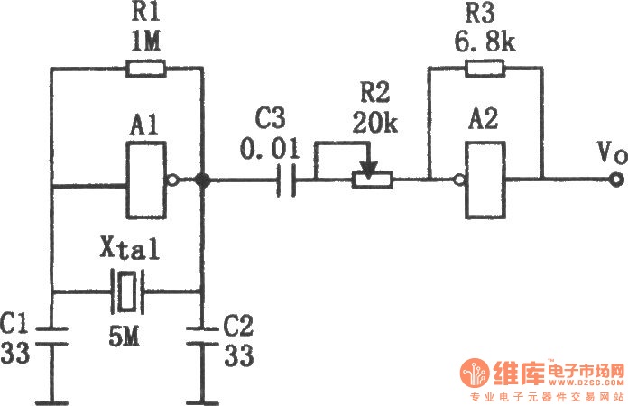
The sine wave generator composed of an inverter is illustrated in the chart. This circuit can produce a high-stability sine wave at frequencies exceeding a few megahertz. In the diagram, A1 and the crystal oscillator create an oscillating circuit,...
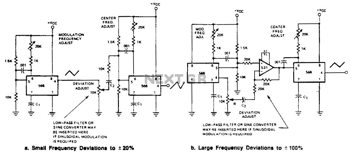
Two FM generators are presented for low frequency applications with a center frequency of less than 0.5 MHz. Each generator utilizes a 566 function generator as a modulation generator and a second 566 as the carrier generator. Capacitor C1...
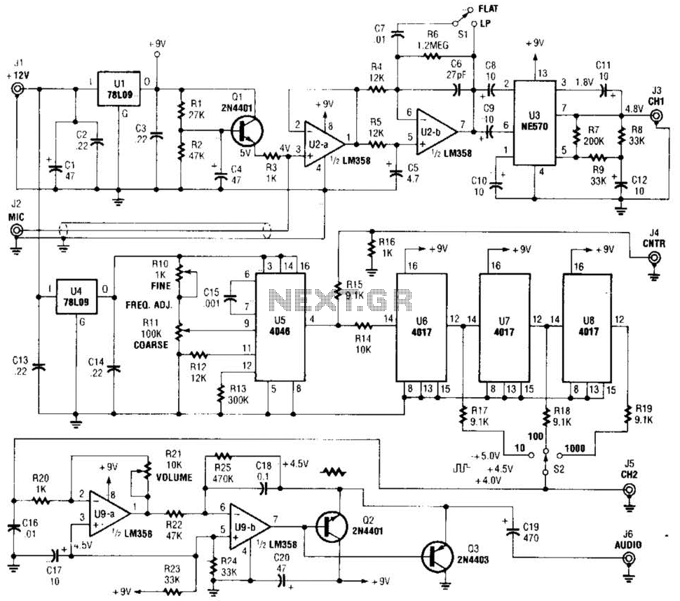
The precision audio frequency generator consists of several sub-circuits: an audio amplifier/filter circuit, an automatic level control, a variable voltage-controlled oscillator, a frequency divider circuit, an integrator, and an audio output amplifier. An electret microphone element is utilized to...