
Crystal Activity Tester Circuit

The circuit utilizes two sections of a 7400 NAND gate IC, configured to form a relaxation oscillator. The oscillator generates a square wave signal, which indicates the activity of the crystal under test. The output from the oscillator is fed into a rectifier circuit, typically consisting of a diode, to convert the AC signal into a DC voltage suitable for driving the next stage.
The rectified output is connected to the base of an NPN transistor. When the oscillation is detected, the transistor is turned on, allowing current to flow from the collector to the emitter. This current flow can then illuminate an LED, providing a visual indication of the crystal's activity. The LED serves as a simple yet effective feedback mechanism, allowing for easy monitoring of the crystal's operational status.
In an alternative setup, as indicated in the description, a meter can be used in place of the LED. This configuration allows for more precise measurement of the oscillation amplitude or frequency, providing valuable data for analysis. The meter can be calibrated to display specific values, offering a quantitative assessment of the crystal's performance.
Overall, this circuit is a practical solution for testing crystal oscillators, providing both visual and measurement capabilities depending on the configuration used. The use of a 7400 IC ensures reliability and ease of integration into various electronic applications. This circuit will check a crystal for activity. Two sections of a 7400 act as an oscillator and its output is rectified and drives an npn transistor that switches an LED (Fig. A). In Fig. B, a meter replaces the LED.
Related Circuits
When the tank is empty, the wires within it are open-circuited, causing the 180K resistor to pull the switch low, resulting in the switch being open and the LEDs being OFF. As water begins to fill the tank, the...
The regenerative effect of a 4-quadrant inverter necessitates power dissipation in some form. In large industrial drives, this power is typically re-inverted back onto the national grid. However, for smaller applications, implementing a braking circuit is advisable. For low-power...
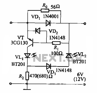
During the charging process, the green light-emitting diode (LED) VLi indicates that the battery is sufficiently charged, while the red light-emitting diode (LED) VLz illuminates when the battery is low. The circuit involves two light-emitting diodes (LEDs) serving as indicators...
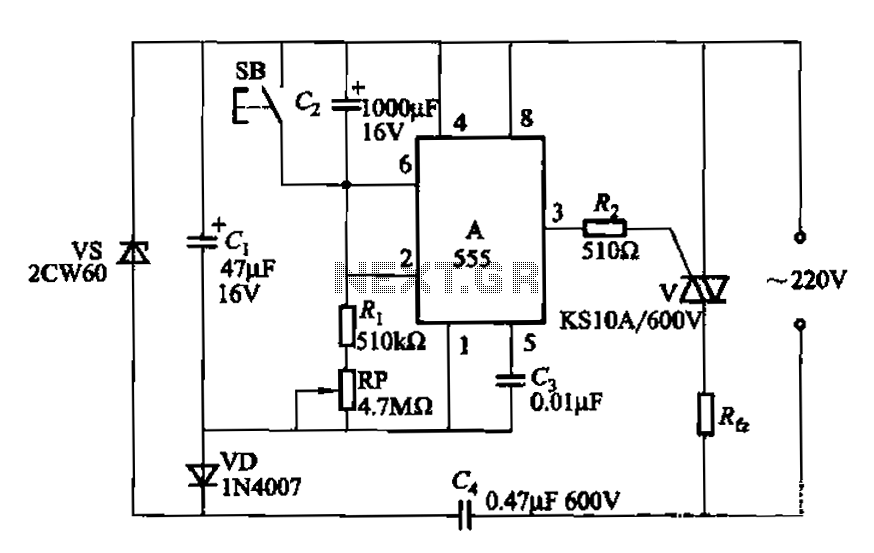
The circuit utilizes a 555 Integrated Circuit (IC) configured as a delay circuit. It transitions from a low to a high state after a button (SB) is pressed, initiating a delay before the output terminal goes high. The output...
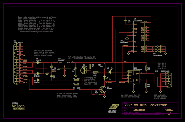
The new version of the RS485 interface addresses the issues associated with RTS control, which was a challenge in the previous design. However, implementing this solution requires a microprocessor, adding complexity to the design. This unit is currently being...
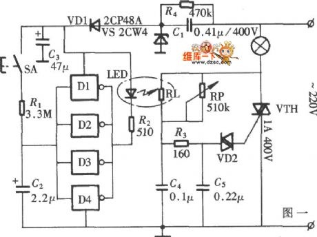
The diagram illustrates a lamp dimmer that gradually increases and decreases light intensity. This feature prevents sudden illumination, which can be a shock to the human eye, and also minimizes damage caused by inrush current when the lamp is...