
Hi-Fi Preamplifier circuit

The circuit in question exhibits a remarkable ability to handle high-frequency signals with minimal distortion, making it suitable for applications that require rapid signal processing. The design likely incorporates high-speed components such as low-capacitance transistors or operational amplifiers optimized for fast switching.
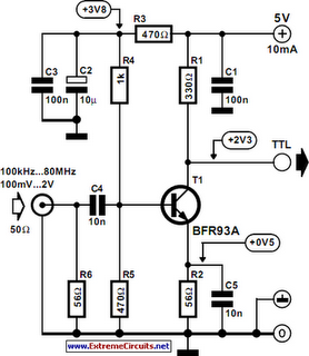
The application of a 100kHz square wave serves as a test signal to evaluate the frequency response and transient behavior of the circuit. The square wave input challenges the circuit to respond quickly to rapid changes in voltage, which is critical in communication and signal processing applications.
Graphical outputs generated using Tina Pro provide visual confirmation of the circuit's performance characteristics, including rise time, fall time, and overshoot. These metrics are essential for assessing the fidelity of the circuit in real-world applications where signal integrity is paramount. The analysis of the circuit's response to the square wave input can reveal insights into potential bandwidth limitations and the effects of parasitic capacitance and inductance.
In conclusion, the circuit's design and performance, as highlighted by the submitted data, demonstrate its potential for high-speed applications, making it a valuable contribution to the field of electronics. Further exploration into component selection and layout optimization may yield even higher performance metrics.This circuit was submitted by Graham Maynard from Newtownabbey, Northern Ireland. It has an exceptionally fast high frequency response, as demonstrated by applying an 100kHz squarewave to the input. All graphs were produced using Tina Pro. 🔗 External reference
Related Circuits

A Countdown Timer Circuit is a project submitted by a group of students for their ECE 130 - Computer Application class on August 31, 2006, at the University of St. La Salle, Philippines. The seven-segment decoder is utilized in...
The circuit diagram features two LT1398 operational amplifiers from Linear Technology, which are utilized to generate buffered color-difference signals from RGB (red-green-blue) inputs. The red (R) input is received through a 75-ohm coaxial cable and is directed to the...
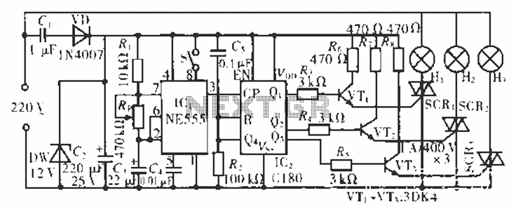
The circuit operates at 220 V AC using a C1 buck converter and a DW regulator. The VD ensures the entire stream is processed, and C2 provides a filtered output of 12 V DC for the voltage supply control...
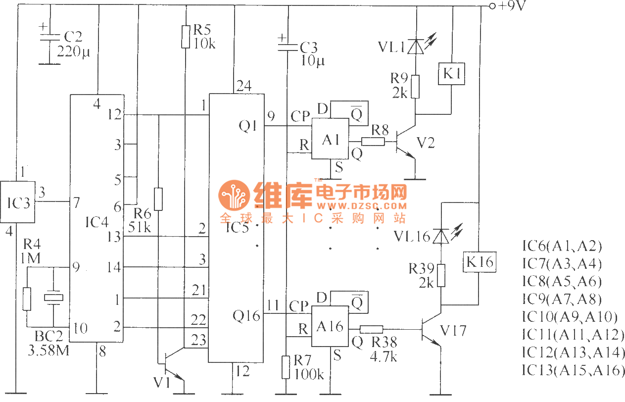
The wireless remote control transmitter circuit consists of control buttons S1 to S16, resistors R1 to R3, a capacitor C1, a regulator diode VS, a crystal oscillator BC1, and DTMF encoder integrated circuits IC1 and IC2. The circuit components...
The image depicts an ultrasonic liquid level indicator circuit. This circuit consists of an ultrasonic transmitter circuit and a receiver circuit. The ultrasonic transmitter circuit includes a 555 timer, resistor R1, variable resistor W1, capacitor C1, and the ultrasonic...

Application of the differential amplifier circuit in OTL amplifier circuits. The differential amplifier circuit is a fundamental building block in various electronic applications, particularly in output transformerless (OTL) amplifier circuits. An OTL amplifier is designed to drive loads directly...