
Crystal Tester

The crystal tester circuit is designed to evaluate the performance and functionality of crystals, which are essential components in various electronic applications, particularly in oscillators and frequency generation. The core of this circuit consists of an oscillator that generates a specific frequency signal, which is determined by the crystal under test.
The oscillator typically employs a transistor configured in a feedback loop that allows it to oscillate at a frequency defined by the crystal's resonant frequency. The crystal is connected to the base of the transistor, and its characteristics influence the oscillation frequency. When the circuit is powered, the transistor amplifies the oscillations, and the resulting output signal is fed to a detector.
The detector serves to convert the oscillating signal into a more easily readable format, such as a voltage level or an audible tone, indicating the presence and performance of the crystal. This output can be monitored using an oscilloscope or an audio output device, allowing for a straightforward assessment of the crystal's integrity and functionality.
In summary, the crystal tester circuit is an efficient tool for testing crystal components, providing a simple yet effective means to determine their operational status and suitability for various electronic applications. The use of a single transistor simplifies the design while maintaining the essential functionality required for effective crystal testing.A crystal tester circuit is very simple, it contains only oscillator and detector inside. This crystal tester circuit uses one transistor for the oscillator and. 🔗 External reference
Related Circuits

This circuit allows for testing quartz resonators within a frequency range of 32 kHz to 24 MHz. The operational status of the quartz resonator is indicated through a diode that signals an LED and emits an acoustic signal. A...
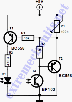
The circuit biases the BC558 transistor, causing LED D1 to flash in response to signals from the remote control. The preset resistor in the circuit sets the sensitivity level. The circuit utilizes a BC558 PNP transistor, which plays a crucial...
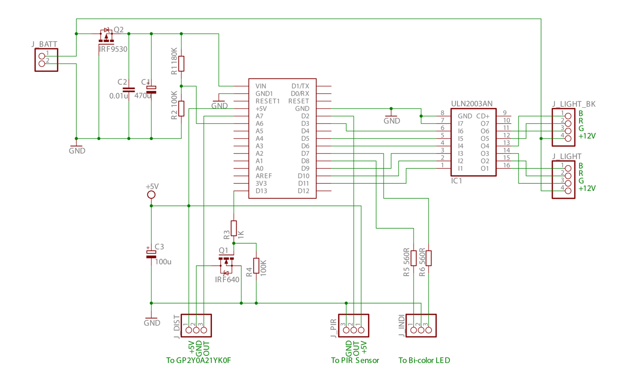
This is the initial phase of an Arduino-controlled PWM RGB LED project, which incorporates distance and PIR sensor control along with a sleep mode feature. The project utilizes an Arduino microcontroller to manage a Pulse Width Modulation (PWM) RGB LED,...
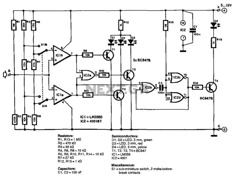
The circuit consists of two comparators that operate with different reference voltages supplied by separate potential dividers. Divider R3/R4/R5 provides a voltage of approximately 40% of the supply voltage (Ucc) to pin 6 of IC1B and about 16% of...
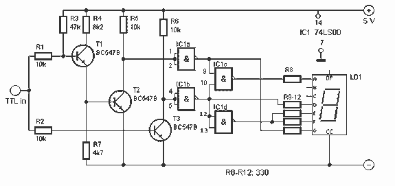
This tester, the logic level digital signals indicate on a 7-segment display. The display shows an H as the input signal is high. When the signal is low, the display shows an L on. If the input is open,...
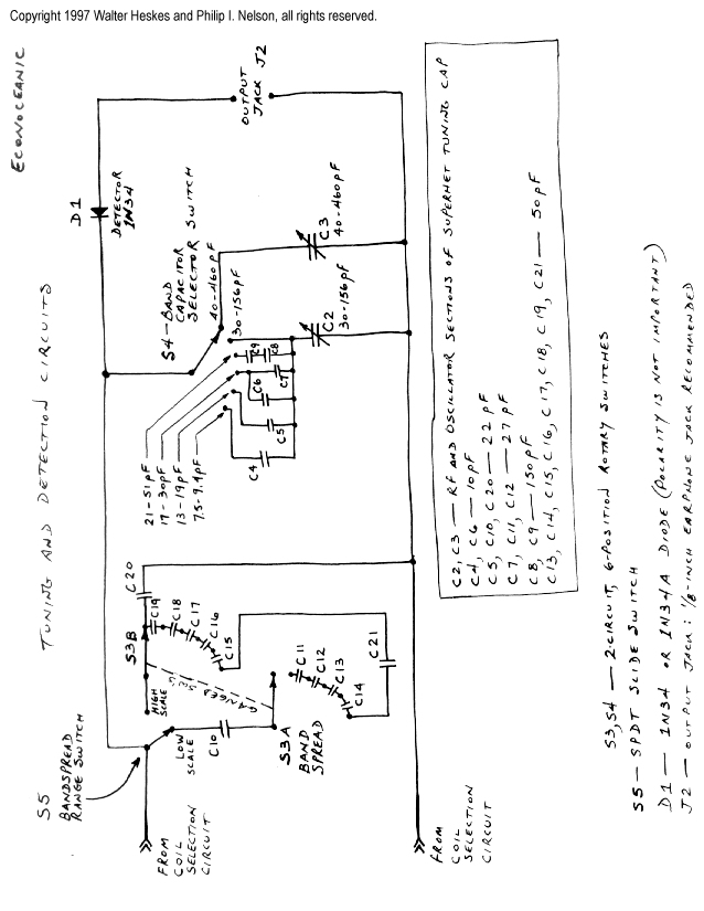
This project merges two significant themes from radio history: crystal radios and shortwave (SW) listening. It has been developed from the ground up by non-resident engineer Walter Heskes. Despite advancements in modern electronics, numerous crystal sets are actively used...