
Single Op-Amp 3 Band Equalizer circuit

The 3 Band Equalizer circuit serves to enhance audio signals by allowing users to adjust specific frequency ranges according to their preferences. The design typically comprises three adjustable filters, each dedicated to one of the frequency bands: treble, midrange, and bass.
The operational amplifier is configured in a feedback loop, enabling it to amplify and modify the audio signal. Each band is controlled by a potentiometer, which adjusts the gain of the op-amp for that specific frequency range. The treble control affects the higher frequencies (typically above 3 kHz), the midrange control adjusts frequencies around 1 kHz to 3 kHz, and the bass control influences lower frequencies (below 1 kHz).
The circuit may include passive components such as resistors and capacitors to define the cutoff frequencies of the filters. By tuning these components, the desired frequency response can be achieved. The output of the op-amp can be connected to a speaker or further audio processing stages, allowing for a customized listening experience.
In practical applications, the 3 Band Equalizer circuit can be integrated into audio devices such as mixers, amplifiers, or standalone equalizers, enhancing sound quality and providing users with the ability to tailor audio output to their liking. Proper layout and grounding techniques should be employed to minimize noise and ensure optimal performance of the circuit.This is a 3 Band Equalizer circuit. This circuit is made to control the treble, middle and bass range. This circuit uses a single op-amp. With single op-amp we. 🔗 External reference
Related Circuits
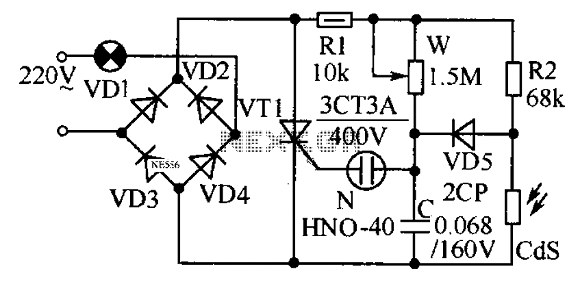
This circuit is designed to automatically adjust the brightness of lights based on the ambient light intensity. In bright conditions, the lights remain off, while in low ambient brightness, the lights are activated. The circuit incorporates a thyristor (VT1)...

This is a circuit known as a Wien bridge oscillator circuit. The circuit features both positive and negative feedback loops and operates under the control of an operational amplifier (op-amp). The oscillation frequency is determined by the RC time...
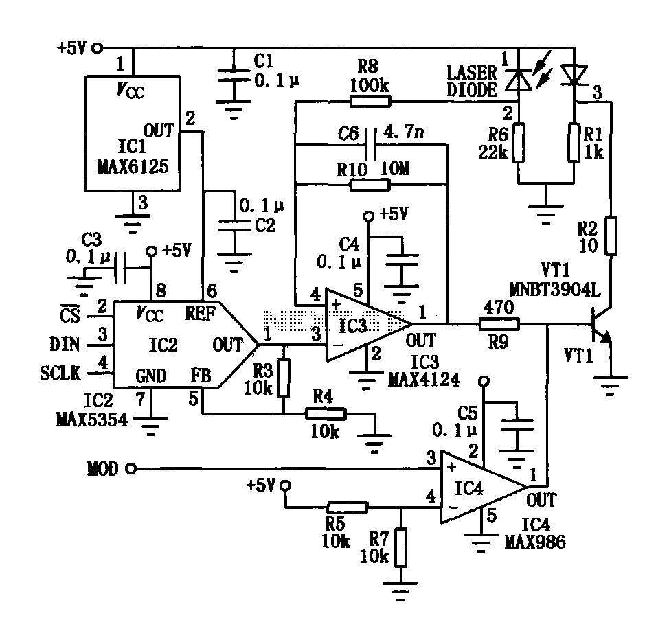
The laser tube drive circuit typically incorporates a photodiode that generates a laser beam proportional to the intensity (optical power) of the current. However, this type of photocell is generally slow and unable to track modulation effectively, particularly for...
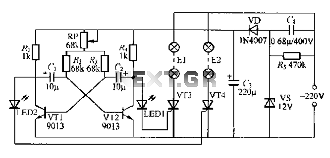
The circuit utilizes a thyristor-controlled unidirectional flashing light string controller. Diodes VT1 and VT2 are connected to a multi-oscillator. Upon powering the circuit, VT1 and VT2 alternately turn on and off. When VT1 is deactivated, VT2 is powered by...

Dual power for each load refers to the operation of two power supplies working simultaneously to handle the electrical load. In the event of a power outage, a contact switch automatically closes all load circuits that are not powered...
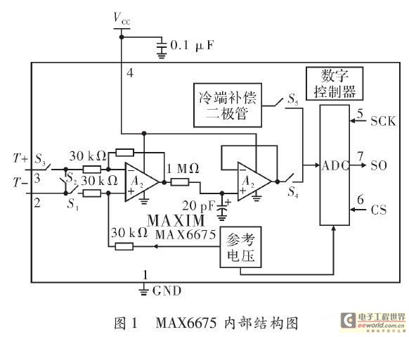
The K-type thermocouple is a commonly used temperature sensor in industrial production and scientific experiments. It can measure temperatures ranging from 0 to 1300 degrees Celsius in various applications, including direct measurements of gas, liquid, and solid surfaces. Its...