
Current amplifier circuit configuration

The current amplifier circuit employs the LM318 operational amplifier, known for its high performance in various applications. The two-stage configuration enhances the gain while maintaining stability and reducing distortion. The complementary push-pull arrangement utilizes both NPN and PNP transistors, which allows for efficient amplification of both positive and negative signal swings.
In this configuration, the output stage benefits from low output resistance, which is crucial for driving loads effectively without significant voltage drop. This characteristic is particularly advantageous in applications requiring high current delivery to the load, ensuring that the amplifier can maintain signal integrity even under varying load conditions.
The circuit typically includes feedback mechanisms to regulate gain and improve linearity. The feedback network can be designed to optimize bandwidth and transient response, making the amplifier suitable for a wide range of applications, including audio amplification, signal conditioning, and sensor interfacing.
Additionally, the LM318 operational amplifier features a wide supply voltage range, which allows for flexibility in design. Proper decoupling capacitors should be placed near the power supply pins to minimize noise and enhance performance. The layout of the circuit should prioritize short traces for high-frequency signals to reduce parasitic capacitance and inductance, which can adversely affect the amplifier's performance.
Overall, the described current amplifier circuit configuration is well-suited for applications demanding robust performance and reliability, thanks to its thoughtful design and the inherent capabilities of the LM318 operational amplifier.Current amplifier circuit configuration is shown in Fig., Followed by a two-stage operational amplifier LM318 complementary push-pull amplifier having an output resistance anti -low, with a load capacity features.
Related Circuits

The timer is activated by the zero-crossing voltage pulse. The time constant is defined by the combination of C5 and the resistors R14 and R15, which determines the conduction angle. The transistors T2 and T3 prevent the power switch...
You will need to go to extremes with the heatsink (fan cooling is highly recommended). It was originally intended for "light" intermittent duty, suitable for an equalised subwoofer system (for example using the ELF principle - see the Project...
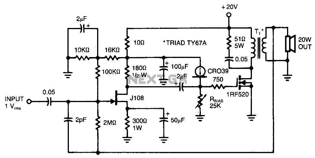
This amplifier provides 20 W of power to an 8-ohm load utilizing a single IRF520 transistor driving a transformer-coupled output stage. The design resembles the audio output stages commonly found in many low-cost radios and phonographs. Distortion remains below...
The water tank overflow liquid level sensor alarm circuit is a straightforward electronics project suitable for school students. Previous discussions have covered numeric water level indicators and water level controller circuits, which are more complex and intended for engineering...
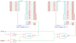
The memory component of the Mark 2 system is quite straightforward. It consists of two 32K SRAM chips, which are actually FRAM due to availability, but this does not impact functionality in this context. The selection of these chips...
This audio noise filter circuit is a bandpass filter designed for the audio frequency range. It effectively filters out unwanted signals that fall below or above the audio frequency spectrum. The audio noise filter circuit operates as a bandpass filter,...