
current controlled oscillator

The circuit operates by utilizing the principle of inductive saturation, where the inductance of the toroidal core decreases as the magnetic field strength increases due to the applied current. The oscillator circuit can be designed using a feedback configuration that incorporates the inductance of the toroid, allowing the frequency to vary in response to changes in the controlling current.
The oscillator can be constructed using a basic feedback oscillator topology, such as a Colpitts or Hartley oscillator, where the inductance of the toroid is a key component in determining the oscillation frequency. The frequency of oscillation (f) can be expressed as:
f = 1 / (2π√(L * C))
where L is the inductance and C is the capacitance in the circuit. As the current through the secondary winding increases, the inductance L decreases due to saturation effects, resulting in a higher frequency output.
The choice of the toroid core material and geometry is critical for achieving the desired inductance values and saturation characteristics. The FT37-43 core is a ferrite material that offers a good balance of inductance and saturation properties for this application.
In practical implementation, the circuit should include a method for measuring the output frequency, such as a frequency counter or an oscilloscope, to monitor the changes in frequency corresponding to the applied current. The use of a variable power supply can facilitate experimentation with different supply voltages to optimize circuit performance.
Overall, this circuit presents a valuable tool for exploring the behavior of inductors under varying current conditions and can serve applications in current sensing, feedback control systems, and educational demonstrations on magnetic saturation phenomena.This circuit was in EDN`s "design ideas" section in the March 5, 2007 issue. It`s a fairly simple circuit and an easy way to investigate how the inductance of a toroid (or any core) is changed by saturation, which in this case is caused by applying a current to a secondary winding. With this circuit, the oscillator frequency is a function of the co ntrolling current and so it can be used to measure current without direct ohmic connection to the circuit. I originally used 16 turns on an FT37-43 toroid for about 100uH, but it wouldn`t oscillate until I increased supply voltage from 5 to about 12 volts, and applying the measurement current would stop oscillation.
The frequency was over 150kHz. I did a new coil using a slightly larger FT37-43 with 50+ turns to give 1. 63mH. I wound four turns onto the toroid for the measurement winding. Frequency would move around (rise) after each adjustment, either due to some time constant or because current was changing below the 0. 4 A-t level. (100mA on the meter times four turns. ) Supply voltage was 5. 07 VDC. In some cases it seems to do better with higher supply voltage. The article hinted that this technique wouldn`t be repeatable enough for an accurate current measurement technique.
That`s probably true. For order-of-magnitude measurements or detection of overcurrent, it would be fine. It could also be used in a feedback loop (PLL) to control frequency using current and inductance as opposed to the traditional varactor method. This measurement could also be used to infer the inductance (and permeability) changes with current. In my example, 4 ampere-turns approximately doubled the frequency. Since frequency is proportional to the square root of inductance, the inductance was reduced by a factor of four (4).
🔗 External reference
Related Circuits
This circuit is an enhanced Hartley oscillator, which allows for frequency adjustment within a specified range by altering the base current. The output signal amplitude exceeds 6V when tested with a 6kΩ load resistance, making it suitable for use...

The circuit is constructed using a 555 oscillator (IC1) and an LM386 audio amplifier (IC2). The 555 functions as an astable oscillator, with its output capable of retriggering the circuit. When the switch (S1) is engaged, it activates the...
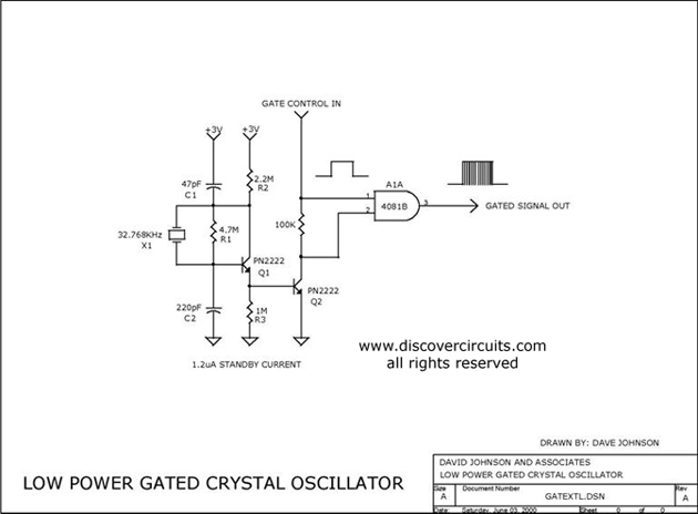
The circuit controls the output of a continuously operating 32KHz crystal oscillator, directing it to the input of a C-MOS buffer when clock pulses are required. This technique addresses the issue of a slow-starting crystal oscillator by maintaining the...
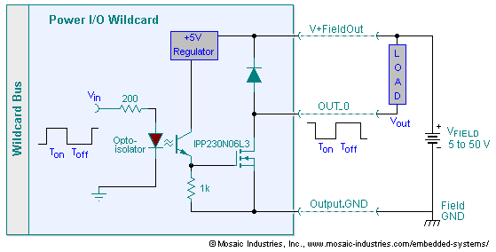
The embedded I/O board offers isolated high voltage switch inputs and eight high current, high voltage DC outputs. It utilizes optically isolated, open drain N-MOSFET transistors functioning as solid state relays (SSR) to control various resistive or inductive loads....
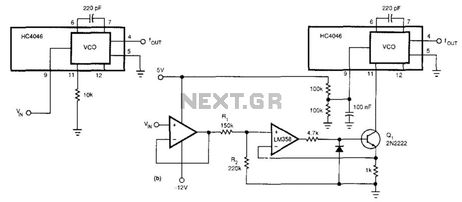
This circuit expands the linear frequency range of an HC4046 from one decade to nearly three decades. An LM358 is utilized as a constant-current sink, replacing the frequency-determining resistor (10 kΩ) connected from pin 9 to ground. For this...
Figure 1 illustrates the VFO oscillator circuit operating within the frequency range of 10.58 to 10.74 MHz. This circuit is a redesigned version of a previously presented Colpitts oscillator, with a clearer representation. The inductor, labeled "L," has an...