
Current-Loop Scr Control

This circuit is designed to facilitate the control of devices such as motors and lighting systems through a 4-to-20 mA current loop, which is a standard in industrial automation for transmitting analog signals. The operation begins with the detection of zero crossings from the 120 Vac line by transistor Q2. This detection is crucial for synchronizing the control signals with the AC line frequency, ensuring that the SCRs are triggered at the correct phase of the AC cycle.
IC1A and IC1B are configured as monostable multivibrators, commonly referred to as one-shots. When Q2 detects a zero crossing, it sends a pulse to IC1B, which generates a timed output pulse. This output pulse is used to control the state of the SCRs, effectively allowing for the modulation of power delivered to the load.
Simultaneously, IC1A is responsible for managing the timing of capacitor C2. When triggered, IC1A causes Q1 to discharge C2, which subsequently begins to recharge through R2. The timing characteristics of this process determine the frequency and duty cycle of the output signal to the SCRs, thereby directly influencing the power delivered to the load.
The optoisolator serves to provide electrical isolation between the low-voltage control circuit and the high-voltage SCR drive circuit, enhancing safety and preventing noise from affecting the control signals. SCR1 and SCR2 are the primary switching devices that control the load, and their triggering is directly influenced by the input current from the 4-to-20 mA loop. This allows for precise control over the operation of the connected devices, making it suitable for applications where variable control is necessary, such as in dimming lights or adjusting motor speeds in response to varying input signals.
Overall, this circuit offers a robust solution for controlling high-power devices through a low-power control signal, ensuring reliability and safety in industrial applications. This circuit allows a 4-to 20-mA current loop to control an isolated SCR drive. IC1A and are one-shots. Q2 detect s zero crossings of the 120 Vac line, which triggers one-shot IC1B. IC1A causes Ql to discharge C2. When C2 recharges through R2, it triggers IC1A, and the optoisolator and SCR1/SCR2. Triggering of SCR1 and SCR2 is a function of input current, which can control motor speed, light intensity, etc.
Related Circuits
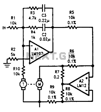
The tachometer, mounted on the same shaft as the DC motor, functions as a generator, producing a DC output voltage that is proportional to the motor's speed. A summing amplifier, labeled as Al, manages its output to ensure that...
If EAGLE is not available, a full working version can be downloaded from CadSoftUSA. A zip file containing the EAGLE schematics is provided. The EAGLE software is a widely used electronic design automation (EDA) tool that facilitates the creation of...
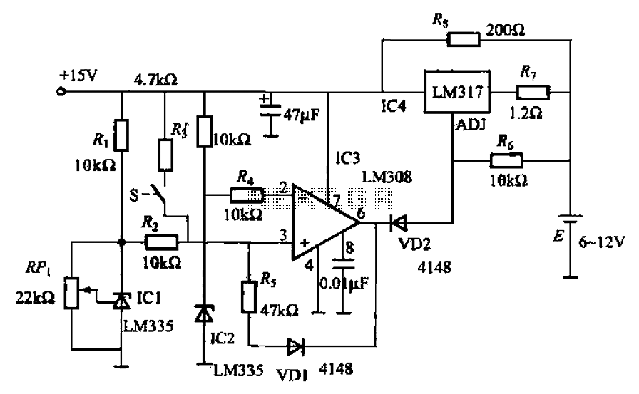
When fast charging a nickel-cadmium battery, the temperature control circuit, as illustrated in the accompanying figure, is designed to monitor the battery temperature to regulate the charging current. The circuit consists of Icl to IC3, which forms the temperature...
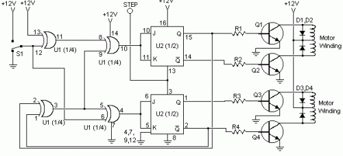
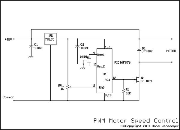
This circuit is constructed using standard components and can be easily adapted for computer control. By utilizing inexpensive surplus transistors and a stepper motor, the overall cost of the circuit can be maintained at under $10. The described circuit is a...
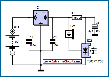
This compact circuit is designed to verify the basic functionality of an infrared remote control unit. It operates on the straightforward principle of connecting a piezo buzzer directly to an infrared (IR) receiver integrated circuit (IC). This approach is...
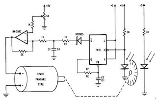
A simple encoder circuit for a DC motor can be constructed using the provided circuit diagram. The system includes the HA-2542 operational amplifier, a small 12 V DC motor, and a position encoder. During operation, the encoder generates a...