
Current source circuit diagram of the operational amplifier and Darlington transistors

The described circuit employs a Darlington transistor configuration utilizing the BSY86 transistor to achieve high current gain. The output current is effectively managed through a combination of fixed and variable resistances, enabling fine control over the output characteristics. The adjustable resistor R, coupled with the RP1 potentiometer, provides a means to set the desired output current level, which is crucial in applications requiring precise current control.
The use of a 10k ohm potentiometer (RP1) is significant as it allows for a broad range of current adjustments, from a minimal 5µA to a maximum of 40mA. This flexibility is particularly useful in circuits where load conditions may change, ensuring that the output current remains stable and within specified limits. The incorporation of three inputs (A, B, C) further enhances the circuit's versatility, permitting alternative configurations depending on the application's requirements.
The adjustment of the emitter potential to ground through RP2 to -0.6V is a critical feature, as it establishes a reference point for the operation of the Darlington pair. This configuration can improve the linearity and response of the circuit, especially in applications involving signal amplification or current regulation. Furthermore, the ability to set the positive terminal potential to -12V enables the circuit to operate within a defined voltage range, optimizing performance while minimizing the risk of component stress.
Overall, this circuit design illustrates the effective use of a Darlington transistor in conjunction with adjustable resistive components to achieve a stable and controllable output current, suitable for various electronic applications.As a result of the Darlington transistor circuit BSY86 the output current is large. Output current 150 ohms maximum limit, the output current is adjusted by the resistor R by t he RP1 potentiometer, and maintained constant independent of the load resistance Rl. FIG potentiometer RP1 using 10k Europe, the current can be adjusted within the range of 5uA ~ 40mA. Op amp inputs A, B, C three partially available instead of confining potentiometer RP1, then the emitter potential BSY86 can be adjusted to the ground by RP2 -0.6V, the sliding contact of the potentiometer regulator positive terminal potential to -12V, then the resistance R and potentiometer RP1 can be canceled.
Related Circuits
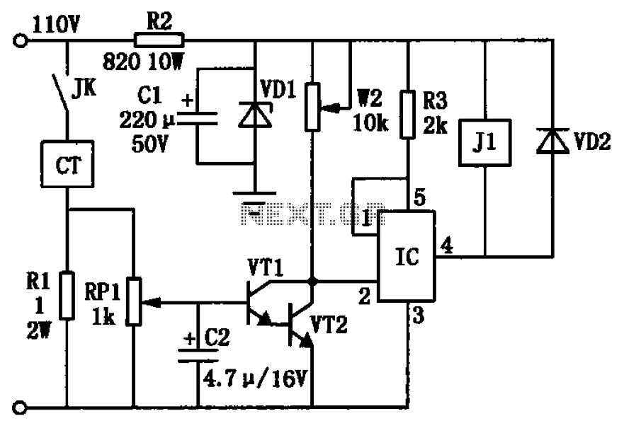
The circuit depicted in the figure utilizes a +24V power supply derived from a 110V power source through an electromagnetic chuck. When the electromagnetic chuck circuit is activated, the contact JK closes, enabling the operation of the magnetic chuck....
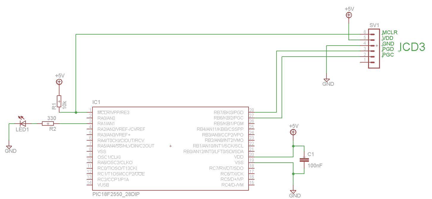
The LED blinks as expected, then pauses for an indefinite duration, flashes again a different number of times, and turns off again, displaying no discernible cyclic behavior. It activates without any external input, indicating that there is likely no...
This project involves a ding-dong doorbell circuit utilizing the 555 Integrated Circuit (IC). In a previous article, a simple doorbell circuit using the UM66 IC, a CMOS three-terminal melody IC, was discussed. The current circuit employs the NE555 IC...
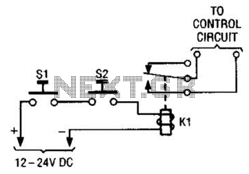
The simple two-hand safety control switch consists of two pushbutton switches connected in series; both must be depressed to energize the relay. The two-hand safety control switch is designed to enhance safety in applications where the operation of machinery or...
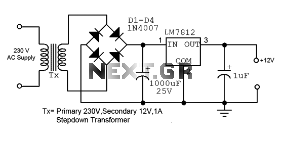
This is a straightforward 12V power supply circuit diagram. It features a fixed voltage output and is based on the LM7812 voltage regulator integrated circuit. The 12V power supply circuit utilizing the LM7812 voltage regulator is designed to provide a...
The first choice is usually an integrated circuit designed for the purpose. A typical assortment can be seen on this National Semiconductor page. Discrete designs can also be built with readily available transistors or op-amps, and many designs are...